Chapter 1: Forces Acting on the Bolted Flange Connection
A. An Overview – Forces Acting on the Bolted Flange Connection
A bolted flange connection is a complex mechanical system whose components must be selected and assembled properly to provide reliable sealing over a wide range of operating conditions. All of the various components of the assembled bolted flange connection are important to the proper operation of the joint. The components consist of the piping, or vessels, the flange(s), the gasket(s) and bolts. In addition to the components themselves, the joint design and assembly are critical to the long-term operation of the joint. This Handbook will focus on the practical aspects of component selection and assembly and for design, it will reference the appropriate design code.
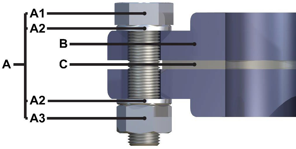
Bolted Flange Connection
A=Fastener (A1=Bolt, A2=Washers, A3=Nut); B=Flange; C=Gasket
A gasket is used to create and retain a A seal between two surfaces that are stationary – as opposed to a dynamic seal which is between two moving parts (ex: rotating or reciprocating). These static seals aim to provide a complete physical barrier to contain the fluid within the pipe or vessel and any potential leak paths a) between the surfaces of the flange or b) through gasket material itself. The application may be intended to remain closed indefinitely (such as a pipeline) or in some cases, repeated opening and closing is required (such as a door seal).
B. Creating the Seal
To achieve a successful seal, the gasket must be resilient enough to conform to any irregularities in the mating surfaces. The gasket must also have sufficient tensile strength to resist sealing element squeezing or flowing out between the mating surfaces as a result of pressure or other forces in the system. The seal is created by the clamping forces acting upon the gasket surface, compressing the gasket and causing the gasket to conform to and fill, flange imperfections. The conformance of the gasket material to the bolted flange connection surface under the compressive load (contact pressure) fills any leak paths and prevents the escape of the contained fluid from the bolted flange connection within a specified leakage rate (or tolerance).
Additional information on generating the initial seating stress can be found in Chapter 4: Installing Gaskets Correctly – Full Guide on Joint Assembly or in ASME PCC-1.
Once seated, a gasket must be capable of overcoming minor alignment issues, flange sealing face imperfections and operating variations such as, but not limited to:
- Non-parallel flange faces
- Misaligned flanges (Figure 3)
- Distortions, troughs, or grooves
- Surface waviness (deviation) (Figure 4)
- Surface scorings (Figure 5)
- Other surface imperfections (Figure 6)
- Flange deformation or warping of the flanges (ex: bowing) from applied forces on the flanges. Often this is due to incorrect gasket selection and may result in failure.
- Allowable temperature range relative to the equipment and/or system.
- Allowable pressure relative to the equipment or system.
- Ambient conditions such as outside temperature or outside elements such as chemicals that may come into contact with the gasket.
- Startup and shutdown processing variations
- Hydro test pressure during leak testing
- System internal cleaning/flushes
Refer to ASME PCC-1 Appendix A for additional details on flatness and defects.

Misaligned bolted flange connections

Bolted flange connection surface wavines

Surface scorings
Other surface imperfections
C. Maintaining the Seal
When the bolted flange connection is assembled, the gasket is subject to compressive load between the faces of the flanges. The compressive load is the force which is often generated by bolts under tension. The compressive load on the gasket must be high enough to compress the gasket into the surface finish of the flanges to fill any potential leak paths. In order to maintain the seal throughout the lifetime of the assembly, sufficiently high residual gasket load must remain on the gasket to minimize leakage. Under operating conditions the compressive forces on the gasket is reduced by the hydrostatic end load and influenced by other factors, such as thermal expansion behavior of flanges and bolts, lever arms, etc.
The hydrostatic end load is the force generated by the internal fluid pressure acting to separate the flanges. The residual gasket load is the compressive load minus the hydrostatic end load. The gasket itself is also subjected to radial forces due to the internal pressure tending to extrude the gasket through the flange clearance space. To maintain the seal integrity, the residual gasket load must be greater than the internal pressure, usually by some multiple. This multiple depends on the gasket material, gasket type and level of tightness required.
In addition, safety factors are generally recommended to ensure the residual gasket load is sufficiently higher than the load required to maintain the seal. Safety factors are generally applied to allow for any relaxation of the gasket compressive forces and to accommodate the application process involved.
For non-metallic (soft) gaskets where the tensile strength of the gasket material may be less than the internal fluid pressure, there must be adequate conditions that resistance to extrusion such as serrated or phonographic finish on the flange faces.

Forces in a bolted flange connection
A=Flange/Bolt Load; B=Hydrostatic End Load; C=Internal (Blow out) Pressure; G=Gasket
D. Forces Acting on the Bolted Flange Connection
The most common way to generate the compressive load required to seal a bolted flange connection, is through bolts. The bolts, as shown below, when tightened act like springs, pulling the flanges together. These bolts need to be stretched enough to keep the load on the gasket as the system is pressurized (during startup) and pressure and temperature is cycled (during normal usage). Additional loading above the minimum load required to seal, will give the bolted joint flexibility to absorb these load changes and a safety margin to maintain the seal as these system forces fluctuate.

Bolts acting like springs
A=Bolt (Spring) Stretch; B=Opposite Force Pulling Flanges (Spring) Together
Bolt yield strength is a measure of the bolt load required to stretch the bolt and still allow it to spring back to its original length. If the bolt is overstretched and is loaded beyond its yield strength, the bolt will not “spring back” when the load is removed. Continued tightening of the bolts will not necessarily increase gasket load or stop a gasketed joint leak and may lead to bolt failure. Caution should be used to avoid overloading bolts which can cause them to stretch beyond their yield strength and actually result in lower than expected loads exerted on the gasket.
The minimum bolt load should be at fifty percent (50%) of bolt yield strength to ensure the “spring” is stretched enough. The bolt load typically used is at eighty percent (80%) or even one hundred percent (100%) of bolt yield; if the calculation method and assembly is very accurate. Modern recommended calculation methods such as EN 1591-1, include tolerances on assembly methods for example, so the use of one hundred percent (100%) bolt yield can be acceptable. However, this recommendation should be tempered by the amount of gasket and flange stresses generated and ensuring that the applied load will not overload, damaging the gasket or flange.
The bolted flange connection will lose compressive load due to system relaxation. If the bolt is not stretched enough, the gasket residual load may drop below the load required to maintain a seal, thereby, causing a leak.
Bolts come in a variety of grades, each with individual yield strength and properties. Proper bolt selection is critical to the proper assembly of a bolted flange connection joint. See more Chapter 3: How to Select a Gasket
Friction between the bolt, nut and the flange threads is a force often overlooked during gasketed joint assembly. When determining the torque required to properly tighten the bolts, a friction factor (or K-Factor refers to force lost to friction or other forces during the tightening process. Inadequate lubrication, for example, can result higher torque readings but a smaller percentage of the force actually being applied to the gasket.)
Bolted flange connection tightening should be controlled to insure proper bolted flanged connection assembly. Chapter 4: Installing Gaskets Correctly – Full Guide and consult the ASME PCC-1 Guidelines for additional information.
E. Other Factors affecting the Seal
After the initial assembly of a bolted flange connection joint, there are many other factors acting on the joint that work to compromise the initial seal (Cycling, Gasket Material, Flange misalignment caused by issues such as insufficient pipe support or thermal expansion. Can result in more stress on the bolts and less to the sealing element).
Most applications undergo pressure and thermal cycles which work to decrease the compressive load on the gasket. Pressure cycles change the hydrostatic end load. Thermal cycles can change the stretch in the bolts through various mechanisms, including bolt material modulus changes due to temperature, differential thermal expansion of the flange component materials and thermal transients, in heat-up and cool-down. These pressure and thermal cycles cause fluctuations on the compressive load of the gasket and may increase the potential for a leak.
Temperature and time can affect gasket materials in a variety of ways. Gasket material degradation due to thermal or chemical exposure can result in a change of material properties, making them less resilient and reducing their ability to spring back under fluctuating loads. Temperature and compressive load can cause creep relaxation (Refers to gasket spreading, thinning or becoming more unstable due to bolt stress combined with elevated temperature. This change in thickness results in relaxation or reduced load on the gasket) in the gasket material itself. Some gasket materials or styles have inherently less creep relaxation and are less susceptible to temperature or chemical exposure than other materials or styles. These factors are covered in Chapter 3: How to Select a Gasket on choosing the correct gasket material.
External bending moments or forces can also affect an assembled joint. Bending moments tend to unload one side of the flanged joint and increase load on the other side creating load changes that can result in leakage. Misalignment of piping and flanges should be minimized. Bolted flange connection misalignment creates additional loads that the bolts have to overcome before the bolt loads can be applied to the gasket. Minimizing alignment issues will help to minimize bending issues, but external forces such as weight of fluid in the piping, or thermal expansion, can create external bending forces. Proper piping supports and piping design can help minimize these external bending forces.