Chapter 3: How to Select a Gasket
Gasket selection can be complex, or it can be as simple as selecting the right color from a shelf in the stockroom. However, selecting the right gasket for a leak-free seal requires much more thought and consideration. Though the best practice for gasket selection occurs during the system and piping design phase. Most of the context which follows is focused on existing bolted flange connections.
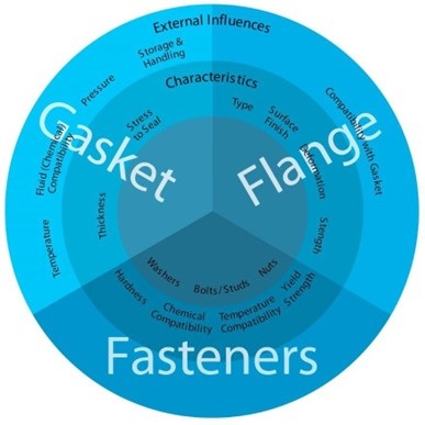
There are four major categories for consideration when selecting the right gasket: gasket related, flange related, fastener related and the gasket-flange-fastener system. Specific gasket related considerations include the temperature, pressure, and fluid interactions against the gasket; as well as the gaskets thickness required stress to seal and storage of the actual gaskets. Of course, there are also special critical applications which require additional industry regulated recommendations, such as oxygen, chlorine services and heat exchanger applications. Flange related considerations include the type of flange in use, its surface finish, flange compatibility with semi-metallic and metallic gaskets due to electrochemical (or “galvanic”) corrosion and flange strength and deformation. Considerations related to the fasteners include material properties of bolts/studs, nuts and washers. When you begin to put these three targeted categories together you must have more holistic considerations such as gasket size, overall joint “tightness”, gasket factors (design) and torque to control joint integrity.
It is imperative to understand that even on an independent level, the complexity of gasket selection is high and when you begin to evaluate the system on multiple levels, the complexity grows exponentially. The following sections will explore the main criteria to ultimately select the right gasket for your application, but it is always advisable to consult your gasket manufacturer for their recommendations on your application as a whole system. Complete an FSA gasket application questionnaire and send it to your preferred manufacturer for a detailed analysis and recommendation.
Considerations of Bolted Flange Connections
A. Gasket Related Considerations
When trying to understand the influences upon gasket selection we must break it down into specific factors which are the most influential: temperature, pressure, fluid (chemical compatibility), gasket thickness, stress to seal, storage and handling. Additional factors are influential in some unique applications and specialty equipment. The following sections look at these factors independently, however, they must all eventually be balanced and evaluated as a whole to make a recommendation. It very important to involve your gasket manufacturer for detailed analysis.
1. Temperature
In general, the temperature of the application fluid is assumed to be the temperature of the gasket. While that is mostly assumed negligible, there are other variables that may be significant in specific applications such as insulation, extreme weather conditions and external heat sources, etc.
Gaskets are affected by temperature in three ways: gross physical characteristics, mechanical and chemical resistance properties. General temperature limits of both gasketing (What is Gasketing Page) products and components are provided in the Table 1 below
- Gross physical characteristics of a gasket and/or its individual components include the material state, oxidation point and general resilience
- Mechanical properties include creep relaxation (sometimes referred to as stress relaxation) and the resulting torque retention capabilities. Under ambient conditions, most gasket materials will not show any significant torque loss. As temperature rises above 90°C (194°F), torque loss becomes a serious consideration and requires a gasket material which will be minimally affected by material degradation or creep relaxation. If the gasket material is suitable for the temperature, re-torquing at an ambient temperature may compensate for torque loss. At temperatures above 90°C (194°F), most applications lose the most torque within the first 24 hours of operation. Refer to Chapter 3D4 for more information on torque & re-torque Torque retention also decreases as material thickness increases. Refer to Chapter 3 Section A4 for more information on gasket thickness.
- Chemical resistance properties can be more difficult to assess on multi-component gasketing products. It is always important to consult with the manufacturer in order to gain specific information on their unique formulations as it pertains to the temperature requirements for your given application.
Table 1 outlines the approximate minimum and maximum temperature limits for common gasketing materials and individual components, based on generally accepted application parameters. While every attempt has been made to provide reasonably accurate values, the data contained herein is a guide and should not be used as a sole source of information for any given product group or type. Variations within the category descriptions between manufacturers, manufacturing methods and material combinations, can significantly affect the listed limits and care must be exercised when such circumstances arise. Please consult the specific manufacturer of the product in question for specific information as it relates to the application.
Consideration should be given regarding the continuous operating temperature of the system. The general temperature limits listed above are generally considered upper and lower limits to the given material or material type under continuous operating conditions. Many manufacturers publish specific pressure-temperature curves for their various non- metallic products as these products are most susceptible to pressure and temperature fluctuations. It should be noted that a given continuous operating temperature limit provided by a manufacturer does not necessarily coincide with a constant continuous operating pressure; rather the relationship is dynamic and should be considered as such. Consult with the manufacturer’s specific information as it pertains to individual operating conditions within the system.
|
Material |
Minimum Temperature |
Maximum Temperature |
|
Flexible Graphite 1 Non-Oxidation Inhibited
Oxidation Inhibited |
-240C (-400F)
-240C (-400F) |
400C to 450C (752F to 842F) 500C to 525C (932oF to 977F) |
|
Compressed Elastomer- Based Fiber2 |
-40C to -30C (-40F to -22F) |
204C to 400C (400F to 750F) |
|
Beater Addition Elastomer-Based Fiber 2 |
-40C to -30C (-40F to -22F) |
180C to 400C (350F to 750F) |
|
Polytetrafluoroethylene (PTFE) 6 |
|
|
|
Virgin PTFE |
-210C (-346F) |
260C (500F) |
|
Expanded PTFE |
-210C (-346F) |
260C (500F) |
|
Filled PTFE |
-210C (-346F) |
260C (500F) |
|
Phyllosilicate8 |
-240C (-400F) |
454C to 982C (850F to 1800F) |
|
Vegetable Fiber |
-30C (-22F) |
121C (250F) |
|
Rubbers/Elastomers 4 and 7 |
|
|
|
Natural (NR) |
-51C (-60F) |
104C (220F) |
|
Nitrile (NBR) |
-30C (-22F) |
100C (212F) |
|
Hydrogenated Nitrile (HNBR) |
-30C (-22F) |
149C (300F) |
|
Ethylene-Proplylene (EPDM) |
-51C (-60F) |
149C (300F) |
|
Fluorocarbon |
-15C (-5F) |
199C (390F) |
|
Chloroprene (CR) |
-40C (-40F) |
121C (250F) |
|
Silicone (VMQ) |
-59C (-75F) |
232C (450F) |
|
Fluorosilicone (FVMQ) |
-59C (-75F) |
232C (450F) |
|
Styrene-butadiene (SBR) |
-46C (-50F) |
100C (212F) |
|
Cork Composition |
-30C (-22F) |
121C (250F) |
|
Metals 5 |
|
|
|
Common Brasses |
-269C (-452F) |
260C (500F) |
|
Copper |
-269C (-452F) |
316C (600F) |
|
Aluminum |
-269C (-452F) |
427C (800F) |
|
Stainless Steel, Type 304 |
-254C (-425F) |
760C (1400F) |
|
Stainless Steel, Type 316 |
-254C (-425F) |
760C (1400F) |
|
Stainless Steel, Type 317 |
-198C (-325F) |
760C (1400F) |
|
Stainless Steel, Type 321 |
-254C (-325F) |
760C (1400F) |
|
Stainless Steel, Type 347 |
-254C (-325F) |
871C (1600F) |
|
Soft Iron, Carbon Steel |
-29C (-20F) |
538C (1000F) |
|
Alloy 20 (UNS N08020) |
-198C (-325F) |
871C (1600F) |
|
Titanium |
-59C (-75F) |
1093C (2000F) |
|
Nickel |
-198C (-325F) |
760C (1400F) |
|
Monel® 400 (UNS N04400) |
-198C (-325F) |
816C (1500F) |
|
Inconel® 625 (UNS N06625) |
-254C (-325F) |
1093C (2000F) |
|
Hastelloy® (UNS N10276) |
-254C (-325F) |
1093C (2000F) |
1 Categories of flexible graphite styles and limits in this chart are referenced from PVRC-SRC.
2 Limits vary depending on the configuration of the binder and fiber-reinforcing system. The minimum range provided is based upon the glass transition temperature (ASTM STP 1249) of the elastomer binder in these types of products. Manufacturers and manufacturing methods vary; when combined with other materials, the minimum temperature limit published by the manufacturer will take into consideration their unique formulation and experiences in static seal applications which may allow for lower limits than those published here. The maximum range provided generally considers the various typical configurations offered by major manufacturers.
3 Maximum temperature limit provided is generally based upon manufacturers agreed maximum continuous operating limits.
4 The maximum temperature limit of rubbers/elastomers can be highly dependent on the operating pressure of the application. Generally a PxT limit is set at <20,000 (psig x oF) for this product group. Consult the manufacturer for specifics based on the application.
5 Minimum temperature limits used in this table for metals are referenced from ASME B31.3 Process Piping as it is considered that the metallic gasket and/or the metallic gasketing components will be limited to the minimum temperatures of the process piping design. Please note that the allowable stress values for metals are greatly reduced at elevated temperatures. Please consult with the manufacturer for specific details based on the application. Additionally, the limits provided are based on the specific material identified: do not use these values for all sub-styles of a particular metal i.e. 304H is different than 304 and 316L is different than 316.
6 The minimum temperature limit for PTFE products has been listed at the temperature just below the points where liquid nitrogen and liquid oxygen will become a solid. This reference point is used in the publication due to the fact that these two substances are the most common cryogenic liquids used in industry. The maximum temperature limit for PTFE products is based on manufacturer’s experience of maximum continuous operating temperature.
7 The minimum temperature limit of rubbers/elastomers has been set to approximately the glass transition temperature (ASTM STP 1249) of the specific material as this change of state from flexible to “glass-like” is considered the limiting factor when using them on any given application.
8 Phyllosilicates come in various types from virtually pure to mixtures with various fillers and binders (for sheet processing and handleability). The maximum temperature range provided in this table is based on published maximums by major manufacturers of this product type.
2. Pressure
In flanged applications, there are four types of pressures that could be considered in gasket selection: working pressure, system design pressure, operating pressure and hydro test pressure.
- Working pressure refers to the flange pressure rating for a given material and operating temperature. Working pressures are provided in commonly recognized codes and standards such as those specified by ASME, CEN, JIS, DIN, etc. For practical purposes related to gasket selection, these codes prescribe the temperature and pressure rating (limits) as well as associated flange dimensions. The higher the pressure class, the more robust the flanges become, providing greater load capability
- System design pressure is the pressure limit specific to a process or equipment and is generally the same as the settings for relief devices. These system design pressures take into consideration system upsets, excursions and pressure spikes
- Operating pressure is the pressure at which the process typically operates under normal conditions. This pressure is lower than system design pressure, to allow for system change/growth, safety, and pressure fluctuation, caused by process controls. It is important to distinguish between the two limits, because a particular gasket material that may be suitable for a given operating pressure, may not be suitable for the system design pressure
- Hydro test pressure is pressure used as a safety check to verify equipment integrity prior to system start-up. A hydro test is generally performed at a given factor (commonly 1.5x) above the working pressure. A gasket must be selected to withstand this hydro test pressure. In some cases, it may be necessary to choose one gasket for the system hydro test and then install a different gasket for operating conditions afterwards
For non-metallic (soft) gaskets, manufactures have defined the maximum pressure limit of the gasket, which is dependent on the compressive load and the operating temperature. In general, high operating temperatures reduce the pressure capability of the gasket. Therefore, care must be taken to ensure that the compressive load, operating temperature, and pressure limit are considered when selecting a gasket for an application. Avoid selecting a gasket by matching the gasket pressure rating to the system pressure alone. Please consult with the manufacturer of the selected gasket material regarding the pressure and temperature ratings of their product.
Examples:
A gasket may have a maximum pressure rating of 103 bar (1500 psi) but may not be used in ASME Class 900 flanges because the application would exceed the maximum compressive load of the gasket.
A gasket may have a maximum pressure rating at ambient temperature of 103 bar (1500 psi) but may be restricted to a 50 bar (725 psi) pressure if the application temperature is 250˚C (482˚F).
For metallic and semi-metallic gaskets, maximum pressure limits are mostly dictated by the available flange load and flange working pressure. Therefore, metallic, and semi- metallic gasket pressure ratings are not directly influenced by temperature.
3. Fluid
The primary purpose of a gasket is to contain a fluid in a mechanical joint. The contained fluid or media can be either gas or liquid. The fluid can range from hot to cold, high to low pH, corrosive to benign, flammable to non-flammable and everything in between. The gasket must be chemically compatible with the contained process fluids and with any fluids used for pressure testing or washdowns. Each gasket material has a different range of chemical compatibility which can change with the process temperature, fluid composition and fluid concentration.
Compatibility is determined by whether the gasket’s physical and chemical properties are adversely affected by exposure to the fluid. Such adverse effects are color change, shrinking and/or weight loss and swelling or softening of the materials. These affects are a result of direct chemical attack, specifically oxidation and corrosion. Direct chemical attack is a very complex subject and can be influenced by many different variables, such as temperature, concentration and duration of exposure. As a rule, the selection of a gasket becomes more critical with increasing temperature, since the rate of chemical attacks generally increases with temperature.
Since some gasket types are made from multiple materials it is critical to ensure that all the materials in the gasket are chemically compatible with the process fluid. We recommend checking with the gasket manufacturer for specifics on chemical compatibility of their specific gasket materials. For fluids or conditions that are not listed in the manufacturer’s tables, the user should seek additional technical assistance for his/her application. It may require an independent study to determine the compatibility of the gasket material with the fluid at the specific operational conditions.
4. Gasket Thickness
Metallic and semi-metallic gasket thickness generally does not alter the gasket pressure and temperature (PT) rating. Therefore, gasket thickness is not a critical factor in gasket selection for metallic and semi-metallic gaskets. Gasket thickness is typically dependent only on gasket construction due to constraints in manufacturing or handling. For example, spiral wound gaskets are generally 3.2mm (1/8”) thick for smaller diameters and up to 7.2mm (0.285”) for larger diameters.
In contrast, the thickness of non-metallic (soft) gaskets affects the gasket pressure and temperature (PT) rating. In general, thicker gaskets will have both a lower pressure rating and a lower temperature rating. This reduction may be compensated with additional compressive load (up to the maximum for the gasket at the given thickness). The maximum compressive load may decrease with increasing gasket thickness.
For non-metallic (soft) gaskets, selecting a gasket thickness can be based on the flange material and/or the flange condition. For metallic flanges, the flange condition may determine the selection of gasket thickness. For special flange materials, such as fiber- reinforced plastic (FRP) and glass-lined steel, other factors, such as flange strength, flange cracking drive and gasket thickness selection.
For non-metallic (soft) gaskets, the goal is to select the thinnest material able to compensate for flange irregularities. (i.e. flange damage, flange warping, uneven flange surfaces, lack of flange parallelism, etc.). Unless the flanges are new, assessing the flange condition can only be done when a bolted flange connection is disassembled. Therefore, it is often difficult to plan for which gasket thickness is best for your particular flange connection. Some general guidance is provided below with respect to the advantages of thin and thick gaskets.
Advantages of a Thin Gasket
Generally thin gaskets are 1.5mm (1/16”) or thinner. A thinner in-service gasket provides the following benefits:
- Higher blowout resistance due to the smaller surface area (at the bore) exposed to the internal pressure
- Lower leak rate due to through-gasket permeation. Smaller surface area exposed to the fluid provides less opportunity for the fluid to permeate through the material
- Better torque retention in the fasteners due to better creep relaxation resistance. For a given material, creep relaxation resistance improves as the thickness decreases
Advantages of a Thick Gasket
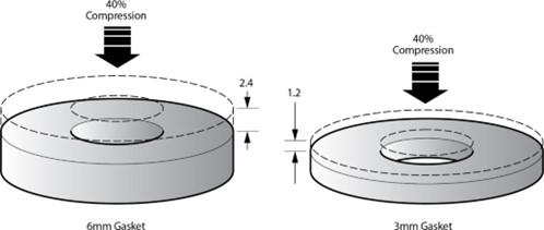
Generally, thick gaskets are 3.2mm (1/8”) or thicker. Typically a thicker gasket can “travel” more upon installation, allowing the gasket to fill in flange irregularities. The amount of “travel” is dependent on both the gasket compressibility and gasket thickness. To illustrate this concept, a 3.2mm (1/8”) gasket compressed 10%, will “travel” 0.32mm (0.0125”); while, a 6.4mm (1/4”) gasket compressed 10%, will “travel” 0.64mm (0.025”). Therefore, the 6.4mm (1/4”) can accommodate twice the amount of flange irregularities. Compressibility is a term often used to describe the gasket’s ability to compress and takes into account compressive load and gasket type.
Accommodating Flange Deviation
The thicker in-service gasket provides the following benefits:
- More “travel” to fill in flange face irregularities
- Lower leak rates by closing off leak paths between the gasket and the flange surface
- More tolerant to flange misalignment
In general, gasket manufacturers have found the following to be true:
- Standard Raised Face flanges in as-new condition will typically utilize 1.5mm (1/16") gaskets, up to 600mm (24") nominal diameter. 3.2mm (1/8”) gaskets are used for flanges greater than 600mm (24”) nominal diameter
- Standard Flat Face flanges often utilize 3.2mm (1/8"), since the flange designs utilize thinner flanges with less rigidity
- Non-Standard pipe flanges, made of glass-lined steel or plastic, will typically utilize 3.2mm (1/8”) gaskets
- Large equipment flanges will typically utilize 6.4mm (1/4”) gaskets to accommodate their typical uneven flange surfaces
5. Gasket Stress
Gasket stress is a term commonly used to describe the unit load on its surface. It is one of the most important parameters of a bolted joint because it directly impacts the ability of the gasket to seal. Since the conditions under which a bolted joint operates during its life can be complex; compressive stress definitions have been established to describe conditions throughout this life cycle. Gasket types respond differently to a given stress
range, so employing the guidance provided by the gasket manufacturers regarding how their materials react is important. A soft and conformable gasket may seal at a relatively low gasket stress, while a hard metal gasket may require much higher stress.
Four Aspects of Gasket Stress
The compressive stress required on a gasket can be viewed in four ways:
- Conform to the Flange Surfaces
A minimum amount of compression is needed to seat the gasket on the flange surfaces. The gasket must conform to the flange’s irregularities to function effectively. If the flanges were perfectly flat and smooth, a gasket might not be needed. With greater imperfections, more compression is needed to form the gasket into that shape - Block the Gasket
Material’s Permeability
Once the gasket has conformed to the flange surface, additional compression may be needed to block any permeability in the gasket body. Permeability through gaskets varies greatly for different types of material, but in almost all cases, leak rates decrease as the compressive load increases. Required stresses, especially in gaseous services, will increase depending on how tight the seal needs to be. These stresses are higher than the minimum stresses that are necessary to make the gasket conform to the flanges. Refer to Chapter 3 Section D.2 for information on joint tightness - Withstand Internal Pressure
When using non-metallic gaskets, the ability of a bolted joint to hold internal pressure depends on friction, which is related to the compressive load on the gasket. The minimum compressive stress will need to be high enough to maintain the friction needed to keep the gasket from blowing out from the internal pressure - Temperature
The fourth consideration for determining an installation stress is temperature. Elevated temperature will create gasket relaxation and subsequent relaxation in the bolt load. Some load losses can be as high as 50 percent of the initial gasket stress. The initial installation stresses need to be high enough to compensate for this effect. This is the reason that some gasket manufacturers recommend a re- torque after the first heat cycle depending on the gasket type (of course, observing the appropriate lock-out and tag-out safety procedures)
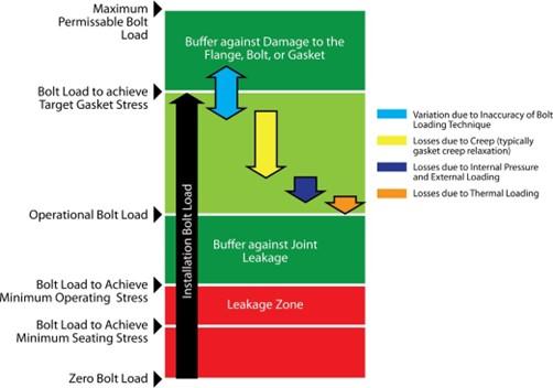
Characterization of Stresses
The minimum seating stress, ideal operating stress, minimum operating stress (considering internal pressure of the system) and maximum operating stress specific to a given gasket material, need to be understood and taken into consideration. While many references to values for these stresses have been published, the most updated reference
is found in an appendix to recently published ASME PCC-1-2010 Guidelines for Pressure Boundary Bolted Flange Joint Assembly. EN1591 Flanges and their joints – Design rules for gasketed circular flange connections also provides terminology and an approach for characterization of gasket stresses and for selecting a target assembly stress.
Relative Gasket Stresses
References to gasket stress in this document are shown, but further explanations are needed. Below are the terms and references used in the text and some suggested guidance agreed upon by gasket material manufacturers.
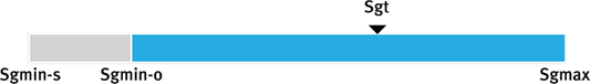
- Minimum gasket seating stress (ASME = Sgmin-S, EN = Qmin) is basically the absolute minimum stress needed to conform to the flanges, assuming that there is little or no internal pressure. Most gasket manufacturers can provide these values on their gasket materials. Often, these values are determined with low-pressure leakage tests on each gasket material. This minimum stress value will normally be used only in flange design calculations
- Minimum gasket operating stress (Sgmin-O) will normally depend on the design pressure of the assembly. It will be higher than the seating stress or Sya value, of the gasket. Most gasket suppliers can provide the minimum operating stress with consideration of the pressure. It is not uncommon for these values to increase with increasing gasket thickness. The minimum operating stress is always lower than the minimum seating stress, however, manufacturers recommend installation stresses higher than both
- Maximum assembly gasket stress (Sgmax) is the
stress that could damage the integrity of the gasket and detrimentally affect
its ability to maintain a seal. Many gasket manufacturers will perform
laboratory tests to determine the maximum stress on a gasket. Many variables
are involved when considering the maximum stress or crush strength of a
material, including surface finish, gasket width, thickness, material
type and temperature. Most manufacturers will test with smooth
surfaces as well as standard ASME/EN serrated flange finishes. Thicker gaskets
are usually less resistant to over compression and crushing. Also, serrated flanges tend to allow for higher compressive loads, because the rougher surface will grab
or hold the gasket better. Smooth surfaces allow the gasket to slip sideways
and split at lower stresses
Because there is a natural variation in any assembly method between calculated and actual compressive stress, most gasket manufacturers will supply a maximum recommended stress that is safely below the actual crush test results. For example, if laboratory tests show damage to a gasket at 172.4 MPa (25,000 psi) stress, the recommended maximum stress might be limited to 103.4 MPa (15,000 psi).
- Target gasket
stress (SgT) is the load that allows
the gasket, as well as the entire joint, to operate at optimal performance and sealability. Additionally, the installation
stress creates a preload in the joint that compensates for overall bolted joint
relaxation after installation and during operation for the service
life of the joint (with consideration given to joint
integrity). ASME PCC-1-2010 recommends that the target stress should be as high
as possible; “The target gasket stress should be selected to be towards the
upper end of the acceptable gasket stress range, as this will give the most
amount of buffer against joint leakage.”
Many reasons exist for using a high-target gasket stress. In assemblies running at high pressures or flanges with large internal diameters, there will be significant unloading of the joint when pressurized. Studies conducted by the Pressure Vessel Research Council (PVRC) on pipe bending stresses showed that the bolt stress in the joint was a major factor in keeping the gasket from leaking. The higher the bolt stress, the more bending force the joint could potentially handle.
System fluctuations in pressure and temperature will affect the retained bolt load in a joint. Since these factors may reduce the load in the bolts, it is good practice to install the bolts at higher initial stresses, if the components are not damaged and bolt material yield is taken into account. Stresses in the bolts will have a direct impact on the stresses in the flanges, so these factors must all be considered when selecting the target gasket stress.
Selecting an Installation Gasket
Stress
Choosing an appropriate gasket installation stress, takes into consideration many factors:
- With equipment such as pumps, valves, actuators,
sight glass assemblies, etc., the manufacturer of those components should be
consulted. For standard plant piping, the designer
or plant engineer
will typically define
the maximum bolt stress
based on the bolt grade, operating temperature, and flange design stresses.
NOTE: This maximum bolt stress is NOT the same as the allowable stress in ASME design calculations, which is typically only 25 percent of yield. This stress limit is much higher because the ASME Code calculations are meant to force the design to have a significant safety factor, and the design stresses are therefore low. - Once the maximum
bolt installation stress is
known, the gasket supplier can provide the recommended gasket
stress. They will need to know the service
conditions for the assembly to select the correct gasket stressa
NOTE: The Y value from the ASME Code calculations should only be used to design the flanges.
The minimum gasket operating stress might be used if the system is going to run at very low pressures. For example, assemblies using pipe and flange materials with low compressive strengths, might need to use the lowest possible gasket stress to affect a seal and avoid damage to the flanges. Flanges running at higher pressures and temperatures will use a stress higher than the minimum operating stress.
The simplest method of selecting the target gasket stress for installation is to calculate the available compressive stress at the maximum bolt stress. This maximum bolt stress is typically determined by the plant engineer and could vary from 40 percent of bolt yield to over 75 percent at some plants. If the available gasket stress at maximum bolt stress is below the maximum gasket stress (or crush strength of the gasket) and above the minimum recommended gasket stress for the operating conditions that can be the target stress.
6.
Gasket Storage and Handling
Although many gasket materials can be used safely after storage for many years, the performance of some gaskets may be compromised due to ageing. Chemical degradation will occur over time as some gaskets are exposed to temperature, humidity, ozone (generated from high voltage electrical sources) and UV exposure.
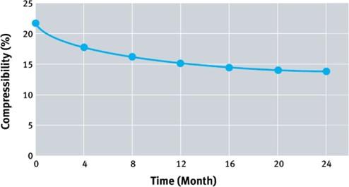
Compressed elastomer-based sheets, as well as finished gaskets, should not be stored for long periods of time. The elastomer used as a binder can age causing degradation of physical characteristics, important to sealing performance. Even aging at ambient temperatures for long periods will have a distinct effect on properties of certain types of gasket materials. This occurs over time primarily because of the chemical degradation of the rubber binder. Figure 34 shows a typical curve of a decrease in compressed elastomer-based fiber gasket material compressibility as a function of time at 25°C (77°F). Primarily, aging is a concern for materials bonded with most elastomers. In general, these gaskets should not be used after about 4 years from the date of manufacture. Those materials with elastomeric binders will inevitably deteriorate over time and even more quickly at higher ambient temperatures. Degradation is also accelerated by intense sunlight and naturally occurring ozone. All of these factors can cause extensive physical damage to the gasket material which will typically result in leakage over time.
Compressibility Change After Aging
Since the mechanical properties of the gasket material play an important role in performance, it is important to control those conditions that accelerate deterioration from aging. The natural aging of the compressed non-asbestos gasket will depend upon the material composition, degree of rubber cure and the manner in which the gasket was fabricated. It is important that the manufacturer recommendations for storage and handling be followed to ensure the longest shelf life for the material.
For metallic gaskets, performance degradation is of little concern; however, it may have an effect on semi-metallic gaskets (specifically, those which are combined with elastomer- bound materials and which may incorporate adhesives to bond substrates). Since homogeneous flexible graphite and PTFE materials contain no binders and are generally considered inert, sheets and gaskets of these materials have virtually an indefinite shelf life.
General guidance from most gasket manufacturers is to store gaskets and gasket materials in a cool, dry location away from heat, excessive humidity, direct sunlight, and chemicals. The optimum storage conditions are defined as 4°C to 27°C (40°F to 80°F) with 40% to 75% relative humidity, in a room with no windows and non-UV or low-UV producing lights, minimal dust and no chemical storage or high voltage electrical sources nearby.
Gasket Storage Recommendations:
- Store in a cool, dry place, away from direct sunlight, UV light, water, oil, chemicals, and chemical vapors
- Do not expose gaskets to excessive heat and humidity or extreme fluctuations of heat and humidity
- Keep gaskets clean and free from mechanical damage (for maximum protection, store in sealed poly bags)
- Avoid accumulation of dust and particulate on gasket faces and edges which may cause compatibility issues with the fluid being sealed
- Store most sheet materials flat where practical and wrapped and/or covered
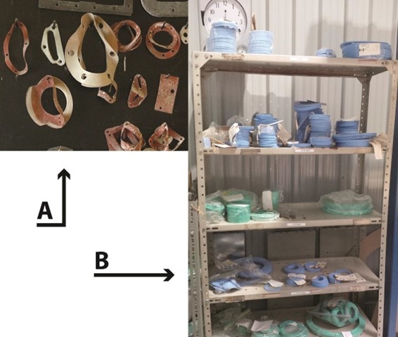
- Store non-metallic (soft) gaskets flat in stacks and avoid hanging them as they may deform
Gasket Storage by Peg Board (A) vs Flat (B)
- For spiral wound gaskets, store them in their original packaging with spacer clips intact. Commonly, gaskets up to 150mm (6”) are stacked in 5 or 10 pieces per bundle and gaskets between 150mm (6”) and 500mm (20”) are stacked in 2 or 5 pieces per bundle using plastic spacer clips to avoid damage to the sealing elements
- For large diameter spiral wound gaskets (>500mm (20”)), keep them on their mounting board and in original packaging
- For metallic gaskets, high humidity and moisture can cause oxidation. Typically, these gaskets are treated to prevent oxidation. Contact us to confirm
The effect of storage and ageing will depend upon the material. Consequently, always consult the manufacturer for advice about storage of specific products.
Gaskets and their packaging should always be handled with care to avoid deterioration and damage and extra care should be taken when handling large gaskets greater than 500mm (20”) in diameter. Whenever gaskets are being transported; individually or in groups; it is preferred that they be kept flat, however, when this is not practical, always make sure that the gasket(s) are adequately supported to avoid any distortion. Typically, transporting gaskets in their original packaging will provide the best protection against distortion until they are ready to be installed.
For individual gaskets, sizes up to 800mm (32”) in diameter, can often be handled by one individual. However, it is recommended to use additional people for larger size gaskets to properly support the gasket and avoid twisting, distortion and breakage.
- 800 - 1000mm (32” - 40”) 3 people
- 1000 - 2000mm (40” - 80”) 4 people
- ·2000mm (80”) and larger 6 - 8 people
When handling spiral wound gaskets, wear gloves and do not hold the gasket by the outer ring only. Failure to adequately support the sealing element and/or inner ring may cause it to dislodge from the outer ring under its own weight, or through flexing and become damaged. Always ensure to support all of the components of spiral wound gaskets through to final installation. It is recommended to keep the mounting board in place for large diameter gaskets until the gasket is situated between the flanges.
Proper handling of gaskets will ensure its integrity is withheld through the transportation and installation stages. Special sizes and gasket configurations usually require special handling on their own. Always consult the manufacturer for recommendations and best practices for your unique conditions.
7. Unique Applications / Specialty Equipment
As with most industrial products, there are many unique applications and pieces of specialty equipment. They often have their own product, material, and specification requirements in combination and in addition to those referenced in 1-6 above. Though it is impossible to consider all the unique applications and specialty equipment, several common ones are briefly discussed below in order to highlight their specific gasketing requirements.
Oxygen Service
All organic and inorganic materials react with both gaseous and liquid oxygen at certain pressures and temperatures. This can cause serious fires and/or explosions. Because of this inherent danger, it is important to select gasket materials which have been tested and certified for use under these severe conditions. Perhaps the most recognized testing and certifying body in the gasket industry is the Federal Institute for Materials Testing & Research (BAM) located in Berlin, Germany. There are many sub-handling requirements for all products in oxygen service, but most applications require the base gasket material to be BAM certified. ASTM publishes two guides (G63, G94) which establish a system for evaluating non-metallic and metallic materials for oxygen service. Table X1.1 in G63, lists several materials commonly used as gaskets in oxygen service, such as PTFE, graphite, and sponge chloroprene (CR) elastomer. Guide G94 tends to not list accepted metals as the determination of such is a very complex process, however, the listed best practice by ASTM for metal selection is to use the least reactive material available with the highest oxygen indices.
Chlorine Service
Chlorine is an aggressive oxidizer that reacts with many metals and organic materials. Service conditions, including contact with dry or wet chlorine, must be taken into account when assessing proper gasket selection. The Chlorine Institute (CI) Pamphlet 95 – Gaskets for Chlorine Service and Euro Chlor in Europe list several gasketing products which have been found as acceptable for use. The Chlorine Institute and Euro Chlor do not endorse any of the listed products; rather the publication reflects information obtained from CI companies in their use and/or evaluation of the gasket or gasket material.
Ethylene Oxide
Ethylene Oxide (EO) is considered very reactive and must be given special attention when selecting proper sealing products. The reactive process is referred to as polymerization and occurs naturally with many products. EO rapidly attacks and breaks down many of the organic polymers and elastomers used to make gaskets and one of the most important points to consider is the rate of deterioration of any selected material. The most visible organization making suggestions on safe products for use with EO is the American Chemistry Council and their publication Ethylene Oxide. Through the American Chemistry Council’s Ethylene Oxide/Ethylene Glycols Panel membership experience, it has been found that the preferred gasket type is a spiral wound gasket with 304SS outer/inner rings, 304SS windings and pure (98% min.) flexible graphite filler. Where spiral wound gaskets are not practical or possible for use, the next choice is often flexible graphite sheets laminated onto a tanged metal core insert. Virgin PTFE has been found to be an acceptable material where the gasket can be captured to minimize creep, however, filled PTFE products are often unsuitable due to effects caused by polymerization of the EO with the filler material (such as glass and barium sulfate).
Fire Safe Requirements
In many refinery and power plants there is the requirement for gaskets to be rated as “fire safe”. One of the more common gasket industry fire test procedures is known as the API
607 Modified Fire Test, which is an adaptation of a fire test for valves. It is common that most metallic and semi-metallic gaskets are accepted as being “fire rated”. There are non-metallic gasketing products such as flexible graphite gaskets which have passed fire tests. In addition, there are a few compressed elastomer-based fiber and PTFE gaskets that have also passed fire tests. Consultation with your gasket manufacturer is important when requiring a fire safe gasket, as they may have many styles for you to choose from to suit your budget and performance criteria.
Nuclear Applications
There are many traditional applications found in the nuclear industry which can use common gasketing types, however, gasket requirements located on the reactor side of the process have very different requirements which must always be carefully scrutinized for safety reasons. Perhaps the most common gasket type used in the nuclear industry is some combination of stainless steel and flexible graphite. Typically there are high purity requirements for the flexible graphite component of the gasket and often special oxidation inhibitors are also required. The nuclear industry has its own regulating bodies and gasket standards can vary depending on operator, reactor type, and region/country. It is important to verify local plant standards and coordinate suitable materials from your gasket manufacturer for these applications.
Food and Pharmaceutical Application
Though these industries are very distinguishable, gasketing specifications and requirements for these two industries are often based upon toxicological tests and component “leaching” tests. The common standards used in these industries include, but are not limited to:
- The Food and Drug Administration (FDA) in the USA has been the primary reference for gasket usage for many years and design specifications often have a requirement for gasketing products to be ‘FDA Approved.’ In virtually all cases, gasket products themselves are not “approved” and only carry a statement of “FDA Compliant”.
- ·The US Pharmacopeia Convention (USP) has developed gasketing standards (USP Class VI <87> and <88>) specifically to the pharmaceutical industry. These new USP standards sometimes requires certification of a manufacturer for a given product in order to verify all of the components, systems and equipment used in the manufacture of the gasket.
- ASME has a bioprocessing standard (BPE-2005) which specifically addresses the “materials of construction of seals in equipment used in the bioprocessing, pharmaceutical and personal care products industries.” BPE-2005 defines 4 classes of seals: Class I, II, III, and Hygienic Fitting Seals.
- The 3-A Sanitary Standards Inc. is largely a USA-based organization focusing on “equipment design for the food, beverage and pharmaceutical industries. 3-A has standards in place to address rubber, rubber-like materials (Standard 18) and plastic materials (Standard 20).
- The European Hygienic Engineering & Design Group (EHEDG) is generally considered Europe’s equivalent to 3-A and has several guidelines which address gasket material selection in various designs of pumps, homogenizers, dampening devices and piping. EHEDG has a harmonization effort underway with 3-A in order to ensure consistency in food safety hygiene practices.
There are many gasket products which meet the codes and standards mentioned above and the user should consult their operations standards, local regulatory bodies and gasket manufacturer for assistance.
Clean/Ultra-Pure Water
Due to the requirement of this industry for ultra-clean equipment (piping, valves, fittings and gaskets), most gaskets can be used in these pure water applications providing they have been cleaned to some specific level as required by the end-user. In many circumstances cleaning procedures similar to those for oxygen service can be employed and will meet the local requirements, however, always consult with the manufacturer and verify that the gasket supplier’s cleaning procedures meets end-user requirements. Typically end-users will perform additional cleaning procedures before placing equipment in service.
Heat Exchangers
Shell and tube heat exchangers pose a unique challenge, due to the relatively low allowable gasket stress designed into the equipment, combined with the temperature cycles and temperature changes (creating a condition called radial shear) from chamber to chamber. Research indicates that there can be a net loss of 20% or more in initial bolt load during the increase in operational temperature of the joint. Care needs to be exercised when making gasket changes in these types of systems.
Many shell and tube heat exchangers come from the factory equipped (OEM) with metal jacketed gaskets, mostly for costs, which usually do not give optimum performance over an extended period of time. Kammprofile, expanded PTFE (ePTFE) and flexible graphite gaskets, can be suitable alternatives to these OEM gaskets.
Kammprofile gaskets (stainless steel serrated cores with flexible graphite covering layers) offer significantly lower required seating stress, resiliency to temperature fluctuations and radial shear inherent in the application. With the varying designs of shell and tube heat exchangers and required partition bars, it is important to communicate measurements and drawings to your gasket manufacturer in order to ensure precision alignment with your equipment.
ePTFE gaskets can be a gasketing option for heat exchanger design that does not require a metal component to the gasket. ePTFE gaskets offer the benefit of conformability and chemical compatibility. Heat exchanger gaskets can be cut from ePTFE sheets. In addition, the use of ePTFE tapes can be a practical solution as the gasket can be formed- in-place around the outside diameter and across the cross-bar(s).
Often in the field, heat exchanger surfaces get damaged, causing difficulty in sealing the metal gasket specified in the original heat exchanger design. When heat exchanger surface re-surfacing is not possible during an outage, graphite joint sealant and ePTFE can be an effective repair method.
B: Flange Related Considerations
The previous section discussed gasket selection in terms of the properties of the gasket itself. The effects of flange and gasket interaction on the resulting joint need to be considered. Certain aspects of flange construction may become the determining factor(s) in the selection of the gasket to produce the desired seal. Below is a review of flange type, flange surface finish and compatibility of the gasket material with that of the flange.
1. Flange Type
There are many types of flanges and associated gaskets in common use. While detailed discussion of flange design is beyond the scope of this document, it is valuable to at least outline some of the common types which are to be found in industrial installations.
While the majority of flange materials are metallic, some applications call for non-metallic flanges, such as reinforced plastic, glass or glass-lined steel. Non-metallic flanges tend to be used for applications which require a greater chemical resistance. Generally, these flanges are less robust and often require gaskets that can be seated under lower gasket stress. Operating temperatures and pressures are usually less severe. It is important to work directly with the gasket manufacturer for non-metallic and lined flanges as the intricacies of creating a tight seal are more complex than standard metallic flanges.
Common Flange Types
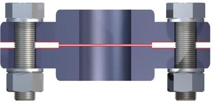
Raised face flanges
Raised face flanges are probably the most common flange type. The flange contact surfaces are raised, and the gasket is non-confined.
The outside diameter of the gasket is centered inside the bolt circle. This is often called a “ring” gasket (also sometimes referred to as an inside bolt circle (IBC) gasket). This allows easy installation and removal of the gasket, without having to separate the complete flange system.
Raised Face Flange
Raised face flanges are probably the most common flange type. The flange contact surfaces are raised, and the gasket is non-confined.
The outside diameter of the gasket is centered inside the bolt circle. This is often called a “ring” gasket (also sometimes referred to as an inside bolt circle (IBC) gasket). This allows easy installation and removal of the gasket, without having to separate the complete flange system.
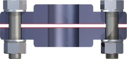
Flat Face Flange
Flat face flanges are normally used where the flange material is made of relatively fragile materials, such as cast iron or plastic. In this case, the gasket is non-confined and is relatively easy to install and remove.
The gasket is in full contact with the flange surface from inside to outside diameters with cut-outs for the bolts to pass through. These are commonly referred to as full face gaskets though several variations are available to meet specific flange load limitations. Ring gaskets can also be used with these flanges, though caution should be taken to avoid flange rotation.
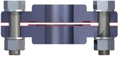
Tongue and Groove Flange
Tongue and groove flanges use a gasket which becomes totally confined on the groove side. The groove depth is equal to, or greater than, the tongue height and normally the gasket has the same width as the tongue.
In this arrangement it is necessary to separate the flanges completely in order to change the gasket. This flange system exerts high seating pressure on the gasket and is not usually recommended for non-metallic (soft) gasket types.
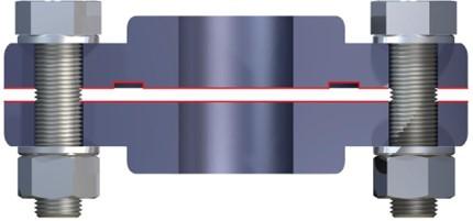
Male and Female Flange (Spigot Flange)
Male and female flanges contain a semi-confined gasket and are available in a variety of styles. The depth of the female flange is equal to or less than the height of the male flange to avoid the possibility of direct contact between the flange faces. Also allows for the proper gasket seating stress when the gasket is compressed. The flange system must be separated to change the gasket.
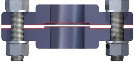
Flat Face and Groove Flange
Flat face and groove flanges use a gasket that is totally confined in the groove. The external face of one of the flanges is plain (flat) and the other has a groove where the gasket is installed. These designs are used in applications where the distance between the flanges must be precise and controlled. When the gasket is seated, the flanges are usually in contact with each other. Only resilient gaskets should be used in this system.
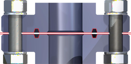
Ring Joint Flange (API Ring Flange)
Ring joint flanges have matching channels in both faces of the mating flanges to accept the ring joint gasket, which is usually made of solid metal. The channels are flat bottomed with sides tapered from vertical with angles of 23 degrees. The gaskets involved are often referred to as RTJ or ring type joint gaskets and are precision machined with specific hardness values.
2. Flange Surface Finish
It is common practice for new flanges to be supplied with a coating to protect the flanges prior to use. Such coatings should be removed from the area to be contacted by the gasket because, when hot, the coatings become soft and reduce the friction between the gasket and flange surfaces. When non-metallic (soft) gaskets are being used this can cause joint failure due to excessive creep induced by the low level of friction.
Metallic flange surfaces may range from a rough casting to that produced by machine lapping and each type of surface influences sealing effectiveness. Surface roughness is usually measured in micro-meters (micro-inches) as an Arithmetic Average Roughness Height (AARH) or Root Mean Square (RMS). The former method is currently preferred. The ideal finish for any particular type of gasket has been a hotly debated subject. There have been studies on the effect of flange surface finish and, in general, most manufacturers provide recommendations about appropriate flange surface finishes for their particular gasket materials.
Commonly used finishes for pipe flanges with non-metallic gaskets are the serrated concentric and serrated spiral (phonograph) finishes. Both finishes are usually made with tools of similar shape and the flange faces are cut to various depths, depending upon the metal. Both serrated finishes consist of a series of cuts, whose width also varies with the type of metal. The serrated spiral finish is a continuous spiral groove, extending from the bore of the flange to the outer perimeter. The serrated concentric finish has definite "hills and valleys", each endless.
"Smooth" finishes which appear to have no perceptible surface irregularities are also quite common. However, when microscopically viewed, the face presents a different picture. The "smooth" finish has wavy contours and slight surface irregularities, which cannot be sealed by naked face-to-face flange contact and a gasket is an essential requirement.
Refer to ASME PCC-1 for additional details on recommended contact surface finish for various gasket types.
There are general rules applicable to surface finishes:
- The flange surface finish has a definite effect on sealing effectiveness.
- A minimum seating stress must be reached in order to flow the gasket material into the irregularities of the gasket surface. A more compressible gasket requires less seating stress than a denser gasket. The total force required to flow the material is proportional to the area of the gasket.
- Bolting force may be lowered by reducing the gasket area or the flange contact area. The difference is primarily a relationship of force to area.
- The closer together the ridge surfaces of a serrated concentric finish and the shallower the grooves, the more the flange area begins to resemble a smooth face flange and hence there is greater contact area. Higher bolt loading is thus required to seat the gasket. The opposite effect occurs as the ridges span wider.
- A serrated spiral finish is more difficult to seal than a serrated concentric finish. Complete flow of gasket material must reach the "valley" surface in a spiral finish, otherwise, a leak path will exist from one end of the spiral to the other end.
- Since gasket materials vary in hardness or resistance to flow, selection of the proper materials and thickness is important in relationship to the flange finish. For example; high temperature and /or pressure applications can use a rough (but controlled) surface finish and gaskets with high resistance to flow; low temperature and / or pressure applications can use a smooth finish, especially with non- metallic(soft) gaskets; and for weak or fragile flanges, non-metallic(soft) gaskets should be used.
- Serrated finishes are generally associated with pipe flange assemblies, whereas "smooth" finishes are likely to be found in flanged joints other than pipe flange assemblies.
3. Flange Compatibility with the Gasket
While all gaskets must be compatible with the fluid, metallic and semi-metallic gaskets must also be compatible with the flange material. Electrochemical (or galvanic) corrosion is an electrochemical process between dissimilar metals that occurs in the presence of a conductive fluid. Electrochemical corrosion can be minimized by selecting gasket and flange metals which are close together on the electrochemical series. Alternatively, the gasket can be sacrificial to minimize damage to the flange.
1. Flange Strength and Deformation
While not necessarily a frequent occurrence, recognizing the flanges’ stress limits of a given bolted flange connection is an important consideration that must be made to ensure integrity of the seal.
Metallic flanges
Metallic flanges are employed most extensively because of their robustness and wide range of suitable mechanical, thermal, and chemical resistance properties. Proper function of a bolted flange connection must also take into consideration the mechanical limits of metallic flanges. If these are exceeded through overstressing it can lead to various forms of damage from excessive flange rotation to failure by Gross Plastic Deformation (GPD) causing the loss of the integrity of the seal. This can occur if flanges are assembled at bolt loads beyond the limits of the flange. In that case, the flanges become the limiting factor for sealing performance. A discussion of the various stresses and the point at which they affect flange damage is beyond the scope of this publication but has been documented in several publications as noted below.
Until relatively recently an established method for practical determination of the limiting stresses for flanges had not been addressed. Earlier research was focused only on bolt and gasket stress limits. The publication of ASME PCC-1 now includes a comprehensive methodology that enables the determination of bolt stress limits taking into consideration pipe flange limits as well. This is included in Appendix O of the PCC-1 document which takes into account not only the type of flange but also the composition of the metal. An example is provided to show what conditions of bolt stress exceed maximum flange stress limits for NPS steel Weld neck Flanges.
Non-metallic Flanges
Fiberglass reinforced plastic (FRP), plastic and other non-metallic piping and flanges are often used in the Chemical Process Industry (CPI). Application of these types of flanges is usually driven by chemical resistance and lower cost compared with the more exotic metals. Design practices for FRP flanges are described in ASME Standard RTP-1-20113 and are beyond the scope of this publication. Appendix NM-9 Installation of RTP Vessels provides guidelines for gaskets, fasteners, torque, lubrication, and other factors related to the bolted flange connection. Mechanical properties of these materials differ substantially from those of metals, and none approach the strength, stiffness, resistance to impact damage, temperature capability and robustness of metals. As a result, flange strength limits bolt torque and consequent gasket stress. Failure modes differ from those of metals because creep and fatigue can result in failure at much lower stresses.
Elastomeric gaskets historically have been applied to these flanges because of their low sealing stress. PTFE is being applied where superior chemical resistance is required but requires a higher sealing stress contributing to some sealing problems with current flange designs. These are being addressed through revisions in flange design methodology.
C. Fastener Related Considerations
The reliability of a bolted flange connection depends largely on the threaded fasteners that are both one of the key and most neglected components in the connection. They work like a spring controlling the internal as well as the external forces to keep the required sealing stress on the gasket. Although threaded fasteners are generally considered a mature technology, significant problems continue to exist with their use. Problems with threaded fasteners arise from insufficient preload, self-loosening, tensile overload, fatigue, galling and thread stripping. While design of a bolted connection provides for a reliable connection; in practice, fastener related failures are not uncommon. Uncertainties about the applied forces, the magnitude of the preload achieved by the tightening process, inappropriate materials being specified and most notably, human error, often results in joint problems in practice. Any problems related to the fasteners can result in serious consequences. On occasion, such failures can have disastrous consequences.
Often the bolts/studs and nuts are considered the principal fastener components; however, washers are also an important part of the system. This fastener system is discussed below.
1. Bolts/Studs
To avoid failure, and at a minimum, compliance with the following must be verified for the fastener:
- Material specification
- Correct thread type and finish
- Sound physical condition
- Correct surface lubrication
A bolt standard must define a series of properties that are required to meet the application needs. The most important properties are:
- Yield strength
- Temperature capability
- Chemical compatibility
- Hardness
The choice of appropriate material standard depends on the industry and application requirements. Many standards are available each of which specifies the chemical composition and the associated mechanical properties.
For pressure vessel and industrial piping applications, ASTM International standards are the major industry reference for North America. Among them, the most representative are:
- ASTM A193/A193M - Specification for Alloy-Steel and Stainless Steel Bolting for High Temperature or High Pressure Service.
- ASTM A320/A320M - Specification for Alloy-Steel and Stainless Steel Bolting for Low Temperature Service.
- ASTM A453 / A453M - Standard Specification for High-Temperature Bolting, with Expansion Coefficients Comparable to Austenitic Stainless Steel.
For Europe, EN and ISO standards are the predominant ones, the most representative being:
- EN 10269 - Steels and nickel alloys for fasteners with specified elevated and/or low temperature properties;
- EN ISO 3506-1 - Mechanical properties of corrosion-resistant stainless steel fasteners Bolts, screws and studs.
- EN ISO 898-1 – Mechanical properties of fasteners made of carbon steel and alloy steel Bolts, screws and studs with specified property classes. Coarse thread and fine pitch thread.
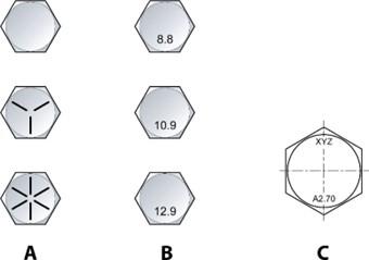
Material Identification on Bolt Head
Yield Strength
For the bolt to operate like a spring, the yield strength must be in balance with the joint. Bolts that apply loads higher than necessary are harmful for the system, as are those that apply insufficient load. The applied load must be sufficient to guarantee the correct gasket seating stress and lower than the flange strength and gasket limit.
When fasteners and joint components are put under tension by tightening the nut (thus inducing a load on the gasket), the fastener and joint components will deform. The fastener will increase in length as the tension in it increases.
The initial stretch of the bolt/stud is the elastic region, within which permanent deformation of the fastener will not occur, even with repeated loading and unloading. The highest tensile force which can be withstood without permanent deformation is known as the elastic limit (also called proof load or yield strength). Fasteners perform most effectively within their elastic region.
Tension loads above the elastic limit will produce some permanent deformation; the fastener will not return to its original length and its effectiveness as a spring clamp will be impaired. At the maximum limit, the ultimate strength of the fastener is also known as the tensile strength.
The mechanical properties of bolts are sometimes expressed in terms of property class. For carbon and alloy steel, it consists of two figures (Cf EN ISO 898-1)
- The first figure indicates 1/100 of the nominal tensile strength in MPa.
- The second figure indicates 10 times the ratio between
lower yield stress ReL (or stress at 0,2 % non-proportional elongation Rp0,2) and nominal
tensile strength Rm, nom (yield stress ratio).
The multiplication of these two figures will give 1/10 of the yield stress in MPa.
For stainless steel, it consists of the combination of a letter and a number (Cf En ISO 3506-1)
- The letter indicate the type of steel (A for austenitic, C for martensitic and F for ferritic).
- The number, the property class, indicate 1/10 of the nominal tensile strength in MPa.
Temperature Capability
A correlation exists between the metallurgical and chemical properties of the bolt material and its temperature capability (i.e. in-use temperature range). The bolt material selection must be based on the yield strength needed as well as the design temperature and flange material. It is crucial to have both bolts and flanges made of materials with similar thermal expansion for proper performance of the fasteners.
Chemical Compatibility
The compatibility of the bolt material with the process fluid and the environment must be considered. Bolts can be subject to chemical corrosion which over time can limit the performance of the fastener and cause problems with disassembly. Bolts can also be subject to electrochemical corrosion and as such, materials should be selected accordingly.
Hardness
Though hardness is not often verified, it is an important consideration for critical applications in nuclear, oil rigs and aerospace. Hardness is an important indicator of whether the required metallurgical processes were followed during manufacture of the fastener. This is an important property check because determination of the fastener material’s chemical composition alone is insufficient to ensure that material properties requirements, such as yield strength, are met. It also ensures the fastener will not be prone to failure, particularly due to Stress Corrosion Cracking (SCC) or brittle fracture at its operating conditions.
2. Nuts
For each bolt/stud specification, there is an associated nut specification. Since both parts interact, it is important to refer to the nut standard as well. The ASTM standard for nuts related to the above for bolts and studs is:
- ASTM A194/A194M - Specification for Carbon and Alloy Steel Nuts for Bolts for High Temperature or High-Pressure Services, or Both. While this standard is indicated for high temperature services, it is also applied to low temperature services
The EN/ISO standards for nuts related to the above for bolts and studs are:
- EN ISO 898-2 – Mechanical properties of fasteners made of carbon steel and alloy steel Nuts with specified property classes. Coarse thread and fine pitch thread
- EN ISO 3506-2 - Mechanical properties of corrosion-resistant stainless steel fasteners Nuts
The tension in the fastener (and hence the compressive pressure on the gasket) is generated by tightening nuts along the threads of the bolt. The threads therefore play a major role in the clamping operation and care must be exercised to maintain their integrity. Threads will strip when the axial forces on the fastener exceed the shear strength of the threads. The main factors which determine stripping strength are:
- The size of the fastener.
- The length of engagement of the threads.
- The strength of the materials from which the bolt/stud and nut are made.
The threads on a larger bolt/stud are “longer” per turn and have thicker roots than the threads of a smaller bolt/stud. This means that the per-thread area which must be sheared to strip the threads is greater on a larger bolt/stud, which means greater stripping strength. Increasing the length of engagement between threads increases the cross-sectional area of the material which must be sheared to strip the threads.
Threads strip more readily when bolt/stud and nut materials are of the equal strength. For optimum safety, use a nut which has a specified proof load 20% greater than the ultimate strength of the bolts/studs. When done this way, the bolts/studs will break before the nut threads strips. Remember, a break is easier to detect than a stripped thread!
Also note the effect of “galling”, which is the cold welding (partial or full) of one heavily loaded surface against another. It is encountered when the surfaces are brought together so intimately that molecular bonds form between mating parts, for example, between a nut and a bolt. This occurs when surfaces are highly loaded, when threads are a tight fit, when lubricants have migrated or dried out and when threads are damaged. This is compounded at high operating temperatures or when corrosion has occurred. It is difficult to eliminate galling, but the following may help:
· use coarse threads, rather than fine
· use the correct lubricant
· select materials for bolts/studs and nuts which in combination are resistant to galling, such as cold drawn 316 stainless steel on cold drawn 316 stainless steel, 400 steel nuts and 316 fasteners, etc.
Finished hex nuts are the most common type. Heavy hex nuts are used in high temperature and high-pressure applications. This is the most common type of nut for flanged joints. Heavy hex nuts are slightly larger and thicker than finished hex nuts.
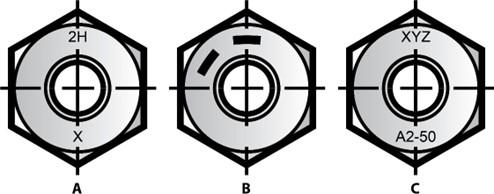
Material Identification on Nuts
A=Americas; B=Europe; C=Stainless Steel
3. Washers
Addition of steel washers to a fastener system is recommended to improve translation of torque input into bolt preload. Washers protect the contact surface of the flange from the turning nut and also provide a smooth bearing surface, reducing friction between nut and flange. This effect is greatest when washers are through-hardened (as distinct from “case hardened”) and washers should be specified as through-hardened.
Washers can:
- Reduce significantly the friction between a turning nut and the joint components. This improves the consistency of the torqueing operation, so improving accuracy and repeatability, while reducing the torque required.
- Reduce problems of fatigue by spreading the load placed by the fastener on the joint.
- Make the interface forces between joint components more uniform, which will improve gasket performance.
- Bridge slotted or oversize holes, facilitating assembly of poorly mated components.
- Prevent damage to joint surfaces.
- Reduce the amount of embedment amongst joint components, thus reducing relaxation after tightening.
Reference ASME PCC-1 for guidance on washer usage and purchase specification.
4. Stainless Steel
In ASTM standards, stainless steel bolts are identified in A193/193M, A320/320M as the B8-grade of alloys. The most popular grades are B8 (304SS) and B8M (316SS). For applications in which chemical resistance properties superior to those of 304SS are needed, 316SS is a next step. Its additional molybdenum content provides improved
pitting and corrosion resistance. Other grades with even higher molybdenum and other element content can be considered for more aggressive environments.
What is not always recognized is that every grade has two classes. The difference between the two classes lies in the strain hardening process. While this process will not affect chemical properties, it will have a significant impact on mechanical properties. For example, bolt grade B8 Class 1 material which is carbide solution treated, has a single yield strength for all diameters; while B8 Class 2 which is carbide solution treated and strain hardened, has yield strength dependent on nominal diameter. Typically, strain hardened Class 2 stainless steel fasteners will provide better results because of their higher yield strength properties; especially when significant assembly load is required to generate a required gasket stress.
In European standard EN10269, stainless steel bolts can also be supplied as annealed solution (AT) or cold work solution (C).
For example, grade X5CrNi18-10 - 1.4301 has:
- When supplied as annealed solution a 0.2% offset yield strength of 190MPa (27.6 ksi) and a tensile strength of 500MPa (72.5 ksi).
- When supplied as cold work solution a 0.2% offset yield strength of 350MPa (50.8 ksi) and a tensile strength of 700MPa (102 ksi).
Thermal effects can significantly change the stability of the initial load. After a pre-stress is applied to a fastener and the service is brought up to an elevated operating temperature, the bolt could elongate further, causing a reduction in load. ASTM A453 Grade 660 bolts are a good option in applications where corrosion resistance, higher yield strength potential and retention of yield strength at elevated temperatures are all important.
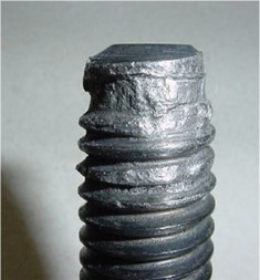
While preventing galling is a concern for all bolt materials, it can be a particular problem with stainless steel fasteners if not properly addressed. Oxide builds up between the threads can lead to fusion of the mating pieces and prevent torque transfer to the assembly.
Galled Stainless Steel Bolt
The table below shows the designations for bolt and nut grades shown in ASTM specifications that are frequently used in bolted flange assemblies.
Note, washers should be made in accordance with ASTM F436 with modification to fit the dimensions of bolted flange connections.
Table 2: Typical ASTM Bolts/Nut Materials used in Bolted Flanged Connections
|
Bolt Grade Designation |
Nut Grade Designation |
Bolt Yield Strength (1) |
Applications |
|
A 193 B7 / L7 |
A 194 2H |
517 to 724 MPa (75 to 105 ksi) |
General Use |
|
A 193 B16 |
A 194 7 |
586 to 724 MPa (85 to 105 ksi) |
Higher Temperatures |
|
A 193 B8 cl. 2 (2) |
A 194 8 |
345 to 689 MPa (50 to 100 ksi) |
Higher temperatures and stainless steel flanges |
|
A 193 B8M cl. 2 (2) |
A 194 8M |
345 to 655 MPa (50 to 95 ksi) |
Higher temperatures and stainless steel flanges |
|
A 320 L7 |
A 194 4 or 7 |
517 to 724 MPa (75 to 105 ksi) |
Cryogenic and low temperature |
1 - Yield strength at room temperature varies with bolt/stud nominal diameter.
2 – Bolt/stud A 193 B8 cl. 1 and A 193 B8M cl. 1 have lower yield strength than the cl. 2 listed in the table. This difference frequently is not recognized and has been the cause of failures.
Selection of
the suitable bolt/stud and nut is a fundamental step toward a reliable flange
connection assembly. Most industrial flange connections are designed in accordance with ASME/PED Codes that reference
bolts/nuts following ASTM/EN standards. This association leads to safer flange
connections. It is always important to check to ensure that fasteners with the
correct specification are used before assembling the joint. To confirm that the bolts
and nuts are correct, check their grade identification mark, as noted in
Figures 43 and 44. All bolts and nuts must have a grade identification mark on one face.
The table below illustrates the “equivalence” between ASTM and EN standards which means that some differences do exist between them. Material characteristics should be verified according to the proposed standard used.
Table 3: Some ASTM / EN Standard Equivalents
|
ASTM Designation |
Material n° |
|
|
A193 B7 |
1.7225 |
42 CrMO4 |
|
A193 B8 Cl 1 & 2 |
1.4301 |
X5CrNi18-10 (*) |
|
A193 B8M Cl 1 & 2 |
1.4401 |
X5CrNiMo17-12-2 (*) |
|
A193 B8T |
1.4541 |
X6CrNiTi18-10 |
|
A193 B16 |
1.7711 |
40CrMoV4-6 |
|
A320 B8 Cl 1 & 2 |
1.4301 |
X5CrNi18-10 –(*) |
|
A320 B8M Cl 1 & 2 |
1.4401 |
X5CrNiMo17-12-2 (*) |
|
A453 Gr.660 |
1.4980 |
X6NiCrTiMoVB25-15-2 |
(*) class 1 is equivalent to annealed solution, class 2 to cold work solution.
1. Specifying a Gasket Size for the Flange System
Industry standards provide nomenclature for gaskets for standard flanges.
ASME
Nominal Pipe Size (NPS)
Pressure Class (Class)
Ring or Full Face Gaskets
Example: NPS 2, Class 150 Full Face Gasket
EN
Nominal Diameter (DN)
Nominal Pressure (PN)
Inner Bolt Circle (IBC) or Full Face Gaskets
Example: DN10 PN40 IBC gasket
ASME provides two standards to consider when specifying standard gaskets for standard flanges made to ASME B16.5 and ASME B16.47 (Series A and B)
- ASME B16.21 Nonmetallic flat gaskets for Pipe Flanges
- ASME B16.20 Metallic gaskets for Pipe Flanges: Ring Joint, Spiral Wound, Jacketed
CEN provides a standard to consider when specifying standard gaskets for standard flanges made to EN 1092 Flanges and Their Joints – Circular Flanges for Pipes, Valves, Fittings and Accessories, PN Designated and made to EN 1759 Flanges and Their Joints – Circular Flanges for Pipes, Valves, Fittings, and Accessories, Class Designated
- CEN EN 1514 Flanges and Their Joints – Dimensions of Gaskets for PN-
Designated Flanges -
- Part 1: Non-Metallic Flat Gaskets With or Without Inserts
- Part 2: Spiral Wound Gaskets for Use with Steel Flanges
- Part 3: Non-Metallic PTFE Envelope Gaskets
- Part 4: Corrugated, Flat or Grooved Metallic and Filled Metallic Gaskets for use with Steel Flanges
- Part 6: Covered Serrated Metal Gaskets for Use with Steel Flanges
- Part 7: Covered Metal Jacketed Gaskets for Use with Steel Flanges
- Part 8: Polymeric O-Ring Gaskets for Grooved Flanges
- CEN EN 12560 Flanges and Their Joints – Gaskets for Class-Designated Flanges
-
- Part 1: Non-Metallic Flat Gaskets With or Without Inserts
- Part 2: Spiral Wound Gaskets for Use with Steel Flanges
- Part 3: Non-Metallic PTFE Envelope Gaskets
- Part 4: Corrugated, Flat or Grooved Metallic and Filled Metallic Gaskets for use with Steel Flanges
- Part 5: Metallic Ring Joint Gaskets for Use with Steel Flanges
- Part 6: Covered Serrated Metal Gaskets for Use with Steel Flanges
- Part 7: Covered Metal Jacketed Gaskets for Use with Steel Flanges
Concerning pressure class designation, it is a frequent misconception that the pressure class is the gasket rating. Class 300 simply refers to a Class 300 flange design and does not necessarily mean the gasket is good up to 300 psi in the actual application. Similarly, PN40 simply refers to a PN40 flange design and does not necessarily indicate the gasket is good for use up to 40 bar. The allowable application pressure of the flange is dependent on temperature and material, which is typically provided in the associated flange standard (such as ASME B16.5) A rule of thumb, for ASME flanges, the maximum pressure at ambient temperature specified for Class 150 is 290 psi and for all the other pressure classes it is 2.5 times the class designation (i.e. Class 300 is 750psi).
2. Joint Tightness
All joints leak at some low but measurable rate. Therefore, the acceptable leak rate for a joint design should be defined by the type of fluid contained, the hazardous nature of the contained fluid, the laws controlling emissions where the joint is installed, the value of the leaking product and other factors.
Tightness Classes
Tightness classes were developed to define the leak rates. These tightness classes are generally defined in the Americas as class T1 through T5 as proposed in the Room Temperature Tightness (ROTT) test procedure. A T2 leak rate is called a standard tightness class and has a helium leak rate of 0.002 mg/sec mm of the gasket outside diameter. The higher the tightness class, the lower the mass leak rate. With each full level of tightness (going from T2 to T3 for example) reducing the leak rate by 2 orders of magnitude, so a T3 tightness class joint would have a leak rate of 0.00002 mg/sec mm.
Gasket tightness is a measure of a gasket’s ability to control leak rate in a joint at a given load. Given all other variables are equal a tighter gasket requires higher internal pressure to drive the same rate of fluid through the joint. Tightness also may be considered as the internal pressure needed to cause a small leak rate in a joint.
Tightness class is defined differently in Europe. Per EN-1591-1, the leak rate is defined by L with a subscript indicating the mass leak rate. For example L1.0 would be a helium mass leak rate of 1 mg/ (sec m) of the mean gasket circumference. The chart below shows the relative correlation between the American “T” tightness class and the European “L” tightness class.
Comparing “T” and “L” Tightness Class
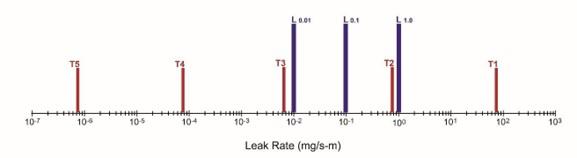
Common Concepts
The initial tightness behavior of a bolted flange joint is determined by the material type and geometry of the gasket, the seating gasket stress, the operating gasket stress level and operating internal pressure. Below are some general considerations to keep in mind when thinking about tightness:
- The tightness can change over time, since the operating stress is susceptible to change during service life of the joint. This is due to joint relaxation from creep of bolts, flanges and gasket and from other load losses caused by variation in service conditions of pressure, temperature and fluid type.
- Leakage at the flange/gasket interface is usually low (except for solid metal gaskets).
- For porous gasket materials, most leakage occurs through the body of the gasket.
- Within the bounds of industry practice, flange surface finish plays a relatively minor role in leakage for most gasket types, other than metal gaskets.
- Leak rates are proportional to gasket diameter as a first approximation for a given gas.
- The ratio of mass leak rates for two different gases is inversely proportional to their respective dynamic viscosities, again as a first level of approximation.
3. Design Gasket Factors
Design Codes/Standards are used to design bolted flange connections. In general, these codes/standards provide guidance on design and selection of flanges, bolts, and gaskets to ensure adequate performance of the joint. Some codes/standards have implemented the concept of joint tightness. Below is a discussion of two main design codes/standards and their respective design gasket factors. Other concepts used in industry are also briefly discussed.
ASME Boiler and Pressure Vessel Code
ASME Boiler and Pressure Vessel Code, Section VIII, Division 1 and 2 contain rules for the design and construction of unfired pressure vessels. The design of bolted flanges requires that gasket constants referred to as maintenance (m) factor and seating (y) stress be used in the calculation. The recommended values given for the gaskets listed in the code are non-mandatory. However, these constants, m and y, must be used in the code formulas unless the designer can justify the use of other values for these constants. Values for constants of specific gaskets are included in Division 1, Table 2-5.1. Additionally, gasket manufacturers publish m and y values for their own specific gasket materials and styles.
NOTE: There is currently no industry standard test to determine the m and y gasket constants, so many gasket manufacturers have developed individual test procedures based on the withdrawn ASTM F586 test method. There is no approved ASME alternative to the code that requires use of these constants.
Bolted Flange Design Methodology
This methodology is based on the Taylor-Forge approach to flange design, which did not include the concept of tightness.
A flange must be designed to create sufficient compressive load on the gasket contact area, to create an initial seal with essentially no pressure in the vessel. The gasket must conform to the flange surface and be sufficiently compressed to compensate for internal voids or spaces that could be detrimental to a seal. The gasket stress required to achieve this initial seal is considered the y constant.
The m value allows the flange designer to determine the compressive load on the gasket required to maintain tightness when the vessel is pressurized. This value is considered a multiplier or maintenance factor. This constant is intended to ensure that the flange has adequate strength and available bolt load to hold the joint together, while withstanding the effects of hydrostatic end force or internal pressure. The design intent is that the flange and bolting will hold the flanges together under pressure and exert an additional stress on the gasket of m multiplied by the internal pressure.
The designer calculates the load required to seat the gasket (Wm2) using y, and calculates load required during operation (Wm1) using m and the design internal pressure. The flange design is then based on the larger of the two calculated values.
Critical Considerations
There are some critical considerations when using the m and y in the two design equations (Wm1 and Wm2); including the fact that they:
- Were originally derived to assist in the design of flanged joint.
- Do not specifically address joint tightness.
- Are often used to determine minimum required bolt loads for assembly purposes.
- Do not consider potential joint relaxation due to temperature effects, torque scatter and the inherent inaccuracies involved in assembly.
- Are more of an indication of minimum load required, when used for assembly purposes and may not correspond to a bolt load required to achieve a certain tightness level under a given set of operating conditions.
- Gasket stress is calculated using an estimated effective contact area, not what may occur with each size and pressure class of flange.
ROTT TEST PROCEDURE
While there are no design codes or standards that are based on gasket factors derived from ROTT, ROTT is often referenced/used to describe gasket sealing performance relative to tightness class in the Americas.
Test Methodology
The ROTT test is performed on a 4-inch NPS gasket using a ROTT test rig with helium gas as the pressurized medium. The test includes two parts.
Part-A represents initial joint tightening and gasket seating. The test includes 5 main gasket stress levels in psi; 1025 (S1), 3040 (S2), 5390 (S3), 7750 (S4), and 10110 (S5) psi, respectively. At each stress level, leakage is measured at 400 psig and 800 psig.
Part-B simulates the operating conditions by performing leakage rate measurements during unload-reload cycles, which are described below
- Part B1 S3-S2-S1-S3
- Part B2 S4-S3-S1-S4
- Part B3 S5-S4-S1
Key Outputs
There are four key outputs from the ROTT test procedure:
- gasket stress vs. leakage rate
- gasket stress vs. gasket deflection
- maximum tightness parameter (Tpmax)
Upon initial seating, gasket tightness normally increases with increasing gasket stress. The maximum tightness parameter, Tpmax, is simply the highest level of tightness achieved during the ROTT test. Normally, the Tpmax value corresponds to the maximum gasket stress level, S5. A high Tpmax is favorable.
- Gasket constants (Gb, a and Gs)
“Gb” and “a” are obtained from the seating load sequence (Part-A) of the ROTT test. “Gb” represents the loading of the gasket at Tp =1, where Tp is the Tightness Parameter. “a” describes the rate at which the gasket develops tightness with increasing stress. For a given gasket material the “Gb” and “a” values are interdependent to determine the gasket stress. Low values of both “Gb and “a” are a favorable and they indicate that the gasket requires a lower gasket stress to achieve a given tightness level.
“Gs” is obtained from the load-unload cycles (Part-B) and is related to the operating conditions of the gaskets. “Gs” shows how sensitive the gasket is to the normal operating conditions such as vibration, shock load, pressure changes and other acts that try to reduce the gasket load and allow more leakage. A lower value of “Gs” is favorable, which indicates that the gasket is less sensitive to unloading.
CEN EN 1591
CEN has published EN1591 Flanges and Their Joint – Design Rules for Gasketed Circular Flange Connections which provides the European standard requirements for designing flanges. This document consists of four parts:
- Part 1: Calculation
- Part 2: Gasket Parameters
- Part 3: Calculation Method for Metal to Metal Contact Type Flanged Joint
- Part 4: Qualification of Personnel Competency in the Assembly of Bolted Joints Fitted to Equipment
- Part 5: Calculation Method for Full Face Gasketed Joints
Design Methodology
The flange calculation described in CEN EN 1591 is a complex calculation that considers flange tightness. As a result, the gasket design parameters also incorporate tightness, L. Gasket manufacturers are responsible for publishing the parameters for their gaskets at the relevant test conditions.
The gasket parameters and associated test method are described in EN 13555 Flanges and Their Joints – Gasket Parameters and Test Procedures Relevant to the Design Rules for Gasketed Circular Flange Connections.
Note: the CEN EN 13555 gasket parameters only apply to Ring (IBC) gaskets, as a DN40 PN40 is the test specimen size.
- PQR – creep relaxation factor, the ratio of the residual and initial surface pressures.
Definition: this factor to allows for the effect of the imposed load on the relaxation of the gasket between the completion of bolt-up and long term experience at the service temperature
- Qmin(L) – the minimum level of surface pressure required for leakage rate class L on assembly
Definition: the minimum gasket surface pressure on assembly required at ambient temperature in order to seat the gasket into the flange facing roughness and close the internal leakage channels so that the tightness class is to the required level L for the internal test pressure
- Qsmin(L) - the minimum level of surface pressure required for leakage rate class L
after off-loading
Definition: the minimum gasket surface pressure required under the service pressure conditions, (i.e.) after off-loading and at the service temperature, so that the required tightness class L is maintained for the internal test pressure
- Qsmax – the maximum surface pressure that can be safely imposed upon the gasket at the service temperature without damage
Definition: the maximum surface pressure that may be imposed on the gasket at the indicated temperature without collapse or “crush”, compressive failure, unacceptable intrusion into the bore or damage of the stressed area of the gasket such that failure was imminent
- EG – unloading modulus of elasticity of the gasket
Definition: this is the additional change in thickness of the gasket or sealing element due to creep between the completion of the loading and the end of the test period
4. Torque
Torque and bolt stretch are two units of measure used to determine the amount of tensile load that is applied to a bolt during installation. Torque wrenches and other tightening devices utilize torque. Tension control fasteners, hydraulic tensioning devices and
ultrasonic fastener analysis, utilize bolt stretch giving improved reproducibility and greater precision of fastening flanged joints.
There are several factors to consider when assembling a bolted joint utilizing torque as a means of proper assembly. Some of these factors are universal in that they should be considered regardless of assembly method.
- Minimum Torque Considerations: Minimum torque may be affected or limited by several factors. They include, among others, obtaining minimum gasket assembly stress, minimum gasket service stress and minimum amount of bolt load (% yield strength)
- Maximum Torque Considerations: Maximum torque may be affected or limited by several factors. They include, among others, maximum flange strength, maximum gasket load and maximum bolt material strength (% yield strength)
- Personnel Considerations: Personnel who are properly trained on proper installation practices greatly increase the likelihood for a successful installation on any given application
Refer to ASME PCC-1 for more discussion on calculating torque, applying torque, and training personnel.
E. Summary…Putting it all together
Unless the bolted joint is properly designed for all the operating conditions in a process, including system upsets, sealing reliability cannot be ensured. Historically, design codes for bolted joints have been successfully based on experimental methodology, while tightness-based approaches were introduced more recently. Both have proven to provide the required system reliability. The more practical and prevalent problem encountered in practice is ensuring the integrity of bolted joints with standard flanges, such as ASME or EN. Standards for the material, dimensions and identification of gaskets employed in these flanges enable proper selection. The proper selection and condition of each component, including the gasket, their correct assembly and installation are fundamentally important to preventing leakage and joint failure. The proper training and qualification of personnel safely employing the appropriate tools, also is essential to joint integrity.
To avoid leakage, the joint must be assembled to a bolt stress level that provides adequate stress to seat the gasket, adequate stress to provide sufficient residual stress on the gasket during operation and be sufficiently low such that no damage occurs to any of the joint components during assembly or operation. For most joints, this concept results in a band of acceptable assembly bolt stress i values that can be depicted as shown in
Figure 45. Several gasket properties must be known to determine the lower limits of assembly bolt stress levels. These include minimum seating stress, percentage gasket relaxation and minimum stress during operation. To establish the upper limits on assembly bolt stress the maximum acceptable gasket stress and the maximum allowable assembly bolt stress that the flange will withstand must be known. A detailed analysis of this concept can be found in PVRC Bulletin WRC-538 Determination of Pressure Boundary Joint Assembly Loads. Such information can also be found in EN1591 Flanges and their joints – Design rules for gasketed circular flange connections.
Acceptable Assembly Bolt Stress