Chapter 4: How To Install Gaskets Correctly – Full Guide
A. Introduction
Often when there are leaks at a flange joint, it is assumed to be a “gasket failure”. The FSA and the ESA both have Gasket Divisions whose membership consists of many of the gasket material manufacturers in the world; report that a high percentage of reported “gasket failures” are Bolted Flange Joint Assemblies (BFJA) that have been poorly designed, installed and/or assembled.
Industry reports less than desirable leak-free results despite all the effort and time to properly design a BFJA that will confine the target media at the target pressure and at the target temperature. Over the past several years, industry awareness of leakage from emissions has created a focus on improved assembly and installation practices as a primary target for corrective action to lead end users towards achieving a leak-free environment.
Of all the considerations that go into designing a successful bolted joint, proper gasket selection and installation are two of the most critical components to creating a leak free BFJA. For more information on selecting a proper gasket, please refer to Chapter 3. Often the skill and knowledge needed to correctly install a gasket are taken for granted. In fact, considerable skill and knowledge are needed to appreciate the conditions and procedures necessary to achieve a reliable (leak-free) bolted joint.
The FSA and ESA recognizes PCC-1 (Guidelines for Pressure Boundary Bolted Flange Joint Assembly) as the industry guideline in the Americas and EN 1591-4 (Flanges and their joints. Qualification of personnel competency in the assembly of the bolted connections of critical service pressurized systems) in Europe for installation of gaskets. These documents represent generally accepted good practices that can be used in conjunction with existing codes.
The FSA and ESA urges the reader to have on hand the most current PCC-1 document including its Appendices. For convenience, we list below bulleted and paraphrased highlights from this document and referenced PCC-1 Appendices where appropriate. PCC-1 focuses primarily on inside the bolt circle flanged joints, but the fundamental principles noted in this document apply to all flange and gasket styles.
The guidelines outlined in PCC-1 cover the assembly elements essential for a high level of leak-tightness integrity of otherwise properly designed/constructed BFJAs. The following table represents the key topics covered in PCC-1 to illustrate the detail required to properly install a BFJA.
B. Consideration of Torque & Frictional Losses
When using, torque tightening methods, there are 3 main factors to consider in order to ensure that the required forces are produced to overcome fastener friction losses:
Torque & Friction Loss
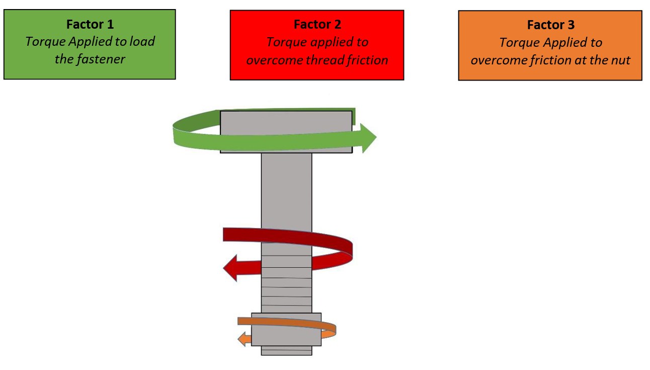
These factors include the assembly load on the fastener spot face (contact surface), the dimensions of the thread and nut and the coefficient of friction between these surfaces. The coefficient of friction is dependent upon the type of lubricant used. The lubricant must have sufficient film strength to prevent direct surface to surface contact which will occur if the lubricant breaks down. There are many types of compositions of lubricants such as aluminum, molybdenum, nickel, copper, ceramic, PTFE, and graphite. The composition of the lubricant must be considered when choosing the proper lubricant for things such as the operational temperature range it will be used in, the bolting material (galvanic corrosion) and the chemical environment that the lubricant is being used in (oxidation corrosion). All these considerations must be considered for the entire service life of the component. Regardless of which type of tensioning method being used (stud tensioner, torque wrench, hammer, and wrench), the lubricant needs to function during both installation and disassembly of the BFJA.
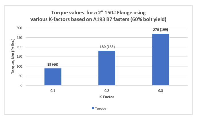
It must be emphasized that friction makes a significant contribution to the recommended torque which must be applied, and hence the use of specified lubricants is crucial for consistent torque control. A change from 0.1 to 0.3 does not result in a 20% change in torque, but a 200% change.
Required Torque vs. K Factor
The value for the coefficient of friction provided
by the manufacturer of the lubricant must be
known to establish an accurate fastener
load. The “Nut factor K” is used to determine the axial load from the torque
applied. It should be advised that “K” is an experimentally derived
dimensionless constant related to the coefficient of friction among many
parameters such as the lubricant
used, bolt sizes, their condition, thread pitch, and other.
This dimensionless constant can be either experimentally derived using ISO 16047:2005 or can be calculated using a
formula that incorporates thread friction, nut on the face friction, thread
pitch, and bolt diameter. It is
recommended that end users perform their own onsite testing with the bolts,
nuts, washers & lubricant that are being used in the installation. This can
be done by using a method such as the Skidmore Wilhelm method where it can be
performed at the installation site and will allow the end user to get real
world values based on the installer, tightening method and application
conditions.
Bolt Conditions and Resulting K Factors
|
Conditions of Bolts and Materials |
K Factor |
|
New steel bolts and nuts, through hardened steel washers under nuts, all mating surfaces coated with moly paste containing 70% solids; bolt and nut temperature of 93-121°C (200-250°F) |
0.08 – 0.10 |
|
New steel bolts and nuts, through hardened steel washers under nuts, all mating surfaces coated with moly paste containing 70% solids; bolt and nut temperature of 21-32°C (70-90°F) |
0.16 – 0.18 |
|
Used steel bolts and nuts with cleaned threads and not washers but lubricated on all mating surfaces with moly paste containing 70% solids |
0.20 – 0.30 |
|
Used steel bolts and nuts with cleaned threads but with no washers and lubrication |
0.40 – 0.50 |
Additional information on nut factors can be found in ASME PCC-1, appendix K
The example calculations below utilizing the above factors will illustrate the importance of accurate K factors.
Table 8: Sample Torque Calculation with varying K Factor
|
Sample torque calculation using various friction factors – 3” 150# Ring gasket with new A193 B-7 studs, 2H heavy hex nuts and hardened washers applying 434 MPa (63,000psi) bolt stress |
|
|
K Factor |
Recommended Torque, Nm (Ft-lbs) |
|
0.16 |
144 (106) |
|
0.19 |
171 (126) |
|
0.40 |
359 (265) |
For final consideration with choosing a lubricant for the installation of a BFJA, the K nut factor provided from the manufacturer must be reliable. It is as important as other engineering components in the system. The manufacturer should be able to advise the percentage of variance for scatter, the particle size and distribution as well as the pressure load resistance otherwise known as the load wear index (LWI) of the lubricant selected.
The performance of the seal is largely dependent upon the correct level of tension in the fastener as described in Chapter 1. Remember that for maximum effectiveness, the load on the fastener should be kept within its elastic region. The fastener should be loaded to ensure that a minimum stretch or strain is applied to the bolting. It is common practice to recommend a bolt stress at assembly that ranges from 40% to 70% of the minimum yield strength of the bolt material. At low stress levels the relationship of toque to axial load will be inaccurate. It is typical to see minimum bolt stress levels above 103.4MPa (15,000 psi) tensile stress up to 70% of maximum yield for assembly stresses in order to reduce torque scatter and inaccuracy.
Joining bolted flange joints is full of inaccuracies & real-world scenarios that must be overcome to achieve the initial gasket seating stress and to achieve a longer term gasket seal (bolt stretch).
C. Outline of Installation, Re-Torque, and Disassembly of Bolted Flange Joints
Using a proven tightening pattern is very important when installing a gasket in a BJFA.
NOTE: All suggested procedures that follow should be performed within the plant guidelines for safety and proper protection of all employees engaged in these activities
Legacy Method Bolt Tightening Pattern
These tightening patterns from vary from the common Legacy Method (Star Pattern) to very intricate installation methods such as the Quadrant Pattern or the Circular Sequence tightening method.
*Please note that the tightening pattern here may be numbered differently than shown in PCC- 1; however, this if for illustration purposes only as the tightening pattern remains the same.
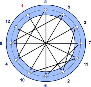
All these methods can be found in Section 11 of ASME PCC-1. Regardless of the method chosen for your gasket installation, the main common goal is to bring the flanges together in parallel as best as possible. Not bringing the flanges together in parallel can create uneven seating stresses on the gasket which can result in crushing the gasket or even a gasket blowout which can occur in areas of non-uniform lower seating stresses.
D. Pre-installation
Before installing a gasket, it should be inspected to ensure that it is in good condition. Check to ensure proper OD, ID and thickness of the gasket are compatible to all operating parameters to which it will be subjected. Many gaskets are fragile and require special handing care to prevent damage, such as large diameter gaskets. A visual inspection of the flange sealing surfaces should be done to make sure that they are free of debris, lubricants, and defects. It is not recommended to use grease or any type of lubricant to temporarily hold the gasket in place nor for ease of gasket removal on disassembly. Verify all fasteners meet all specifications including material, length, thread pitch, and nut thickness. Previously used fasteners need to be inspected for defects such as burrs, galling, corrosion and fatigue. It is accepted practice to check all fasteners to be sure the nuts run freely up and down the length of the threads. If they do not, determine the cause and correct the condition before continuing.
E. Installation of the Gasket and Assembly of the BJFA
With the exception of grooved metal gaskets with covering layers, do not reuse gaskets under any circumstances. Align the new gasket properly to be concentric with flange ID and avoid protrusion into piping flow path. Ensure the gasket remains in proper place during assembly but do not apply lubricant or grease on the gasket or contact surfaces as mentioned above (this does not typically apply to O-rings). Also ensure that flanges are properly aligned and parallel to each other (refer to PCC-1 for information on the allowable tolerances of alignment, rotation and parallelism).
Lubricate load bearing surfaces such as bolt threads, under-head contact area, nut facings and washers, as per the lubricant manufacturer’s recommendations. Do not lubricate coated bolts for first time use.
Initially install bolts and nuts so they are hand tight in the BFJA but not exceeding 20% of the recommended target torque. It is also good practice to number each bolt to assist in proper assembly.
Bolts must be tightened in incremental steps to arrive at the target stress level using a properly calibrated load control device such as a torque wrench, a stud tensioner or similar device. PCC-1 provides many different methods for tightening of the bolts in combination with many different load control devices. Use of any of these combinations are designed to assure proper and even load distribution over the entire area of the gasket contact surface. The reader is encouraged to reference FSA/ESA document (FSA0009) FSA/ESA Gasket Installation Procedures – Assuring Joint Integrity and Maximum Safety which is adapted from PCC-1.
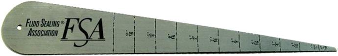
During the incremental torquing steps, it is good practice to measure the flange gap at a minimum of four points at 90 degrees to each other around the flange OD at each step to assure even loading. When possible, it is recommended to use more than four measurement points for flanges larger than 8” in diameter. This can be done easily by using a gap measurement tool or Vernier calipers.
Flange Gap Measurement Tool
It should be noted that over the years there have been many new methods developed where installation time (especially on flanges over 20” in diameter) can be reduced while the final torque accuracy is maintained at an equal or higher level. PCC-1 provides the installer with many of these alternatives with in-depth instruction as to how to properly implement such procedures.
It must be recognized by users and planners that all BFJA’s (flanges, bolts and gasket materials) relax after initial stress is applied. Experience shows that a large percentage of BFJA relaxation happens within the first four hours. It is therefore recommended that before the plant process is energized, a four hour wait period is observed after the initial assembly is completed and a final rotational torque is performed to return the assembly to the target stress level.
G.
Re-torqueing the BJFA after initial
installation
For most materials in the flange system (including gaskets, fasteners, nuts, washers), relaxation sets in after a fairly short time. For soft gasket materials, one of the major factors is the creep relaxation of the gasket. Creep effects are accentuated at elevated temperatures, with the net result that the compressive load on the gasket is reduced, thus increasing the possibility of a leak. Consequently, gasket manufacturers recommend that fasteners should be re-torqued (to the recommended torque at ambient temperature before the process is energized) 24 hours after the initial assembly. Re- torqueing adjustments are not always feasible nor desirable, thus the gasket material with the most suitable torque retention characteristics becomes a higher priority in the gasket selection process. For more complete guidance on re-torqueing, please refer to ASME PCC-1 or the gasket manufacturer for application specific procedures.
Care must be exercised with repeated re-torqueing to avoid damage to the gasket. This is especially important in the case of soft gaskets with a relatively small sealing area, such as ring gaskets, as the stress on the gasket often approaches the maximum allowable seating stress of the material. With larger area gaskets, such as full-face gaskets, the maximum seating stress is typically never reached, thus allowing for more opportunities for re-torqueing before gasket damage occurs.
Elastomeric gaskets and fiber reinforced elastomer bound gasket materials continue to cure in service from start-up as the system reaches final operating temperature. Once fully cured, these gasket materials become hard and brittle and may crack under excessive load. Always consult the gasket manufacturer for advice about re-torqueing, but as a rule do not re-torque an elastomer-based fiber gasket after it has been exposed to elevated temperatures (121°C/250°F).
In many applications, system designs are subject to thermal cycling which can vary from tens of degrees to hundreds of degrees. Special consideration must be taken in the gasket selection process where thermal cycles can be significant as bolt torque retention is reduced with each subsequent cycle. There are many available solutions to combat these conditions and it is best to consult with the gasket manufacturer for optimum material selection.
With respect to hot re-torque, studies have been conducted on the feasibility of re- torquing at elevated temperatures. In general, such practices are not recommended, nor are they safe; however, as the complexity of modern gasket materials varies significantly, it is imperative to consult with the gasket manufacturer on their specific recommendations for hot re-torqueing.
Prior to any joint disassembly, it is essential that plant procedures (lock-out and tag-out procedures) have been followed to depressurize and de-energize the system, including the removal of liquid head from the system, to ensure that the BFJA may be safely opened.
After reaffirming that all pressure on the joint has been released and the joint has been separated, proceed with bolt loosening and nut removal. Good general practice is to loosen the side of the joint away from yourself first to ensure in case of an accidental release that it is directed away from yourself. Disassembly of a BFJA should be conducted in a similar fashion as the initial assembly. Bolts should be loosened in increments and also in a crisscrossed pattern to ensure an even unload. The first loosening should be done at approximately 50% of the original recommended torque. Once joint separation is achieved, proceed with the balance of the bolt loosening and nut removal. An aid such as a hydraulic or manual flange spreader may be used if necessary to separate the joint.
J. Special considerations for Large Diameter
Flange Gasket Options
Spiral Wound and other Semi-Metallic Gaskets - For large diameter spiral wound gaskets, seat the gasket in its mounting on the flange, remove securing straps, then slide the gasket from its mounting onto the flange using an appropriate number of persons to avoid damage to the gasket. Making sure not to grab or handle the gasket by the inner ring and or winding to avoid possibly damaging the gasket.
Form in place gasketing (What is gasketing page) products are typically produced as tapes or “cords” and may be considered for large and/or non-standard flanges. Form in place products are available in a wide variety of widths, and care must be taken to calculate gasket stress in terms of the final compressed width of the product at installation. Consult the manufacturer for help in making this determination. Many form in place products have an adhesive strip on one side to aid in holding the tape in place during installation particularly on vertically oriented flanges. All form in place gasket products require the creation of a joint where the ends of the product meet. There are a number of methods to create joints that vary by the particular product form and material. To best ensure a stable joint, installation should be done such that the joint is located at a bolt hole so that there is a maximum amount of load available to ensure that the joint is adequately compressed. Consult the product manufacturer for specific advice on techniques for making the joint.
For flexible graphite gaskets with large diameters, great care must be taken when handling and moving gaskets into place during the installation process. Wrinkling or creasing of the gasket can create a site for a leakage path to develop. For improved handling, using flexible graphite with a laminated or tanged insert such as 316SS greatly increases the handling ability of the gasket and reduces the risk of damage prior to installation. For large diameter gaskets >20” (500mm) graphite tape can also be used to make a gasket onsite for leaking flanges or emergency repairs. For gaskets with a diameter <20” (500mm) crinkle gasket tape should be used to prevent the gasket material from wrinkling or creasing during installation.